Nissan Altima (L32) 2007-2012 Service Manual: Main line between DLC And ABS Circuit
Diagnosis Procedure
INSPECTION PROCEDURE
1.CHECK CONNECTOR
1. Turn the ignition switch OFF.
2. Disconnect the battery cable from the negative terminal.
3. Check the following terminals and connectors for damage, bend and loose connection (connector side and harness side).
- Harness connector M1
- Harness connector E30
Is the inspection result normal? YES >> GO TO 2.
NO >> Repair the terminal and connector.
2.CHECK HARNESS CONTINUITY (OPEN CIRCUIT)
1. Disconnect the harness connectors M1 and E30.
2. Check the continuity between the data link connector and the harness connector.
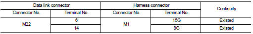
Is the inspection result normal? YES >> GO TO 3.
NO >> Repair the main line between the data link connector and the harness connector M1.
Is the inspection result normal? YES >> GO TO 3.
NO >> Repair the main line between the data link connector and the harness connector M1.
3.CHECK HARNESS CONTINUITY (OPEN CIRCUIT)
1. Disconnect the connector of ABS actuator and electric unit (control unit).
2. Check the continuity between the harness connector and the ABS actuator and electric unit (control unit) harness connector.
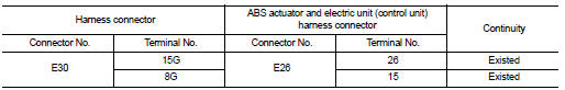
Is the inspection result normal? YES (Present error)>>Check CAN system type decision again.
YES (Past error)>>Error was detected in the main line between the data link connector and the ABS actuator and electric unit (control unit).
NO >> Repair the main line between the harness connector E30 and the ABS actuator and electric unit (control unit).
 Lan system can system (type 2)
COMPONENT DIAGNOSIS ...
 ECM branch line circuit
Diagnosis Procedure
INSPECTION PROCEDURE
1.CHECK CONNECTOR
1. Turn the ignition switch OFF.
2. Disconnect the battery cable from the negative terminal.
3. Check the following terminals and co ...
Other materials:
Preparation
Special Service Tools
The actual shapes of Kent-Moore tools may differ from those of special
service tools illustrated here.
Commercial Service Tools
...
B1065 – B1068, B1070 – B1073 passenger
airbag module
Description
DTC B1065 – B1068, B1070 – B1073 PASSENGER AIR BAG MODULE
The passenger air bag module is dual stage and wired to the air bag diagnosis
sensor unit. The air bag diagnosis
sensor unit will monitor for opens and shorts in detected lines to the passenger
air bag module.
PART LOC ...
Passenger side
Description
Door glass moves UP/DOWN by receiving the signal from main power window and
door lock/unlock switch or
power window and door lock/unlock switch RH.
Component Function Check
1. CHECK FRONT POWER WINDOW MOTOR RH CIRCIUT
Does power window motor RH operate with main power windo ...
