Nissan Altima (L32) 2007-2012 Service Manual: Seat belt warning chime
System Diagram
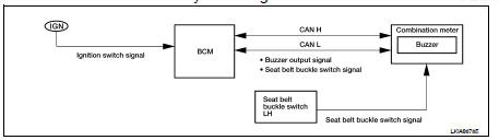
System Description
DESCRIPTION
With ignition switch turned ON and driver seat belt unfastened, seat belt warning chime will sound for approximately 6 seconds.
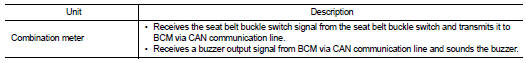
• BCM receives seat belt buckle switch signal from combination meter with CAN communication line.
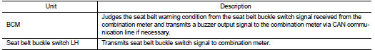
• BCM detects ignition switch turned ON and seat belt buckle switch LH ON. And then transmits buzzer output signal (seat belt warning chime) to combination meter with CAN communication line.
• When combination meter receives buzzer output signal (seat belt warning chime), it sounds the buzzer.
WARNING OPERATION CONDITIONS
If all of the following conditions are fulfilled
• Ignition switch OFF→ON
• Seat buckle switch LH is ON (driver seat belt not fastened)
WARNING CANCEL CONDITIONS
Cancels the warning if any of the following conditions is fulfilled.
• Ignition switch OFF
• Seat buckle switch LH is OFF (driver seat belt fastened)
• 90 seconds have passed since the start of the warning
Component Parts Location
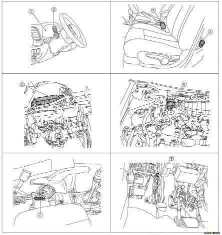
1. Combination meter M24
2. Combination switch (lighting switch) M28
3. Seat belt buckle switch LH B202
4. Door switch LH B8
5. BCM M16, M17, M18, M19 (view with instrument panel removed)
6. ABS actuator and electric unit (control unit) E26
7. Parking brake switch M73 (sedan with M/T or coupe) (view with center console removed)
8. Parking brake switch E35 (sedan with CVT) [view with instrument panel lower cover (LH) removed]
Component Description
 Light reminder warning chime
System Diagram
System Description
DESCRIPTION
With ignition switch in OFF or ACC position, driver door open, and lighting
switch in 1ST or 2ND position, the
light warning chime will sound.
...
 Parking brake release warning chime
System Diagram
System Description
DESCRIPTION
• The combination meter receives the vehicle speed signal from the ABS
actuator and electric unit (control
unit) via CAN communication l ...
Other materials:
Front wiper and washer system
System Diagram
System Description
OUTLINE
The front wiper is controlled by each function of BCM and IPDM E/R.
Control by BCM
• Combination switch reading function
• Front wiper control function
Control by IPDM E/R
• Front wiper control function
• Relay control function
FRONT WIP ...
B2617 starter relay circuit
Description
Located in IPDM E/R, it runs the starter motor. The starter relay is turned
ON by the BCM when the ignition
switch is in START position. IPDM E/R transmits the starter relay ON signal to
BCM via CAN communication.
DTC Logic
DTC DETECTION LOGIC
NOTE:
• If DTC B2617 is displa ...
Precaution
Precaution for Supplemental Restraint System
(SRS) "AIR BAG" and "SEAT BELT PRE-TENSIONER"
The Supplemental Restraint System such as “AIR BAG” and “SEAT BELT PRE-TENSIONER”,
used along
with a front seat belt, helps to reduce the risk or severity of injury to the
dr ...
