Nissan Altima 2007-2012 Service Manual: Can communication circuit
Diagnosis Procedure
INSPECTION PROCEDURE
1.CONNECTOR INSPECTION
1. Turn the ignition switch OFF.
2. Disconnect the battery cable from the negative terminal.
3. Disconnect all the unit connectors on CAN communication system.
4. Check terminals and connectors for damage, bend and loose connection.
Is the inspection result normal? YES >> GO TO 2.
NO >> Repair the terminal and connector.
2.CHECK HARNESS CONTINUITY (SHORT CIRCUIT)
Check the continuity between the data link connector terminals.
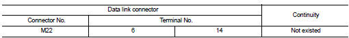
Is the inspection result normal? YES >> GO TO 3.
NO >> Check the harness and repair the root cause.
3.CHECK HARNESS CONTINUITY (SHORT CIRCUIT)
Check the continuity between the data link connector and the ground.
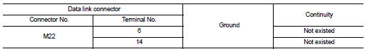
Is the inspection result normal? YES >> GO TO 4.
NO >> Check the harness and repair the root cause.
4.CHECK ECM AND IPDM E/R TERMINATION CIRCUIT
1. Remove the ECM and the IPDM E/R.
2. Check the resistance between the ECM terminals.
3. Check the resistance between the IPDM E/R terminals.
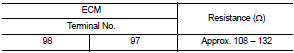
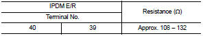
Is the measurement value within the specification? YES >> GO TO 5.
NO >> Replace the ECM and/or the IPDM E/R.
5.CHECK SYMPTOM
Connect all the connectors. Check if the symptoms described in the “Symptom (Results from interview with customer)” are reproduced.
Inspection result
Reproduced>>GO TO 6.
Non-reproduced>>Start the diagnosis again. Follow the trouble diagnosis procedure when past error is detected.
6.CHECK UNIT REPRODUCTION
Perform the reproduction test as per the following procedure for each unit.
1. Turn the ignition switch OFF.
2. Disconnect the battery cable from the negative terminal.
3. Disconnect one of the unit connectors of CAN communication system.
NOTE: ECM and IPDM E/R have a termination circuit. Check other units first.
4. Connect the battery cable to the negative terminal. Check if the symptoms described in the “Symptom (Results from interview with customer)” are reproduced.
NOTE: Although unit-related error symptoms occur, do not confuse them with other symptoms.
Inspection result
Reproduced>>Connect the connector. Check other units as per the above procedure.
Non-reproduced>>Replace the unit whose connector was disconnected.
 IPDM-E branch line circuit
Diagnosis Procedure
INSPECTION PROCEDURE
1.CHECK CONNECTOR
1. Turn the ignition switch OFF.
2. Disconnect the battery cable from the negative terminal.
3. Check the terminals and connectors o ...
 Lan system can system (type 8)
COMPONENT DIAGNOSIS ...
Other materials:
Disassembly and assembly
FRONT SEAT
DRIVER SIDE
Exploded View
1. Headrest
2. Headrest holder (locked)
3. Headrest holder (free)
4. Seatback board
5. Seatback/frame assembly
6. Inner finisher
7. Seat belt buckle
8. Seat cushion trim
9. Seat harness
10. Seat cushion pad
11. Front leg covers
12. Lumbar l ...
USB interface (models with Navigation System)
Connecting a device to the USB input
jack
WARNING
Do not connect/disconnect or operate the
USB device while driving. Doing so can be
a distraction. If distracted you could lose
control of your vehicle and cause an accident
or serious injury.
CAUTION
● Do not force the USB device int ...
B2555 stop lamp
Description
BCM detects the stop lamp status and confirms the stop lamp switch ON/OFF
status. BCM confirms the
engine start condition according to the stop lamp switch ON/OFF status.
DTC Logic
DTC DETECTION LOGIC
DTC CONFIRMATION PROCEDURE
1.PERFORM DTC CONFIRMATION PROCEDURE
1. Depress ...
