Nissan Altima (L32) 2007-2012 Service Manual: DLC branch line circuit
Diagnosis Procedure
INSPECTION PROCEDURE
1.CHECK CONNECTOR
1. Turn the ignition switch OFF.
2. Disconnect the battery cable from the negative terminal.
3. Check the terminals and connectors of the data link connector for damage,
bend and loose connection
(connector side and harness side).
Is the inspection result normal?
YES >> GO TO 2.
NO >> Repair the terminal and connector.
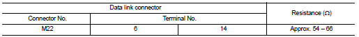
2.CHECK HARNESS FOR OPEN CIRCUIT
Check the resistance between the data link connector terminals.
Is the measurement value within the specification?
YES (Present error)>>Check CAN system type decision again.
YES (Past error)>>Error was detected in the data link connector branch line
circuit.
NO >> Repair the data link connector branch line.
Diagnosis Procedure
INSPECTION PROCEDURE
1.CHECK CONNECTOR
1. Turn the ignition switch OFF.
2. Disconnect the battery cable from the negative terminal.
3. Check the terminals and connectors ...
Diagnosis Procedure
INSPECTION PROCEDURE
1.CHECK CONNECTOR
1. Turn the ignition switch OFF.
2. Disconnect the battery cable from the negative terminal.
3. Check the terminals and connectors ...
Other materials: Warning/Indicator lights (red)
For additional information on warnings
and indicators, see "Vehicle information
display - 5 inch (13 cm) Type A" or
"Vehicle information display - 7 inch (18cm)
Type B".
or
Brake warning
light
This light functions for both the parking
brake and the foot brake systems.
Parking brake indicator (if s ...
Three-point type seat belt with
retractor
WARNING
Every person who drives or rides in
this vehicle should use a seat belt at
all times. Children should be in the
rear seats and in an appropriate
restraint.
Do not ride in a moving vehicle when
the seatback is reclined. This can be
dangerous. The shoulder belt will not
be against yo ...
Precautions on child restraints
WARNING
Failure to follow the warnings and instructions
for proper use and installation
of child restraints could result in serious
injury or death of a child or other
passengers in a sudden stop or collision:
The child restraint must be used
and installed properly. Always follow
all of ...
 BCM branch line circuit
 M&A branch line circuit