Nissan Altima (L32) 2007-2012 Service Manual: Optical sensor
Description
The optical sensor converts the outside brightness (lux) to voltage and transmits the optical sensor signal to the BCM.
Component Function Check
1.CHECK OPTICAL SENSOR SIGNAL BY CONSULT-III

1. Turn the ignition switch ON.
2. Select "OPTICAL SENSOR" of BCM (HEAD LAMP) DATA MONITOR item.
3. Turn the lighting switch to AUTO.
4. With the optical sensor illuminating, check the monitor status.
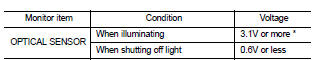
*: Illuminates the optical sensor. The value may be less than the standard value if brightness is weak.
Is the item status normal? YES >> Optical sensor is normal.
NO >> Refer to EXL-53, "Diagnosis Procedure".
Diagnosis Procedure
1.CHECK OPTICAL SENSOR POWER SUPPLY INPUT
1. Turn the ignition switch ON.
2. Turn the lighting switch to AUTO.
3. Check the voltage between the optical sensor harness connector and ground.
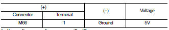
Is the voltage reading as specified? YES >> GO TO 2
NO >> GO TO 4
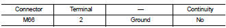
2.CHECK OPTICAL SENSOR GROUND INPUT
Check the voltage between the optical sensor harness connector and ground.
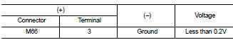
Is the voltage reading as specified? YES >> GO TO 3
NO >> GO TO 6
3.CHECK OPTICAL SENSOR SIGNAL OUTPUT
With the optical sensor illuminating, check voltage between the optical sensor harness connector and ground.
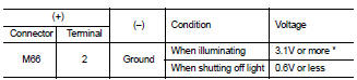
*: Illuminate the optical sensor. The value may be less than the standard if brightness is weak.
Is the voltage reading as specified? YES >> GO TO 7
NO >> Replace the optical sensor.
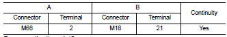
4.CHECK OPTICAL SENSOR POWER SUPPLY FOR OPEN CIRCUIT
1. Turn the ignition switch OFF.
2. Disconnect the optical sensor connector and BCM connector.
3. Check continuity between the optical sensor harness connector and the BCM harness connector.
Does continuity exist? YES >> GO TO 5
NO >> Repair the harnesses or connectors.
5.CHECK OPTICAL SENSOR POWER SUPPLY FOR SHORT CIRCUIT
Check the continuity between the optical sensor harness connector and the ground.
Does continuity exist? YES >> Repair the harnesses or connectors.
NO >> Replace BCM. Refer to BCS-96, "Removal and Installation" .6.CHECK OPTICAL SENSOR GROUND FOR OPEN CIRCUIT
1. Turn the ignition switch OFF.
2. Disconnect the optical sensor connector and BCM connector.
3. Check continuity between the optical sensor harness connector and the BCM harness connector.
Does continuity exist? YES >> Replace BCM. Refer to BCS-96, "Removal and Installation" .
NO >> Repair the harnesses or connectors.
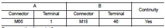
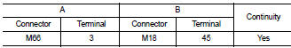
7.CHECK OPTICAL SENSOR SIGNAL FOR OPEN CIRCUIT
1. Turn the ignition switch OFF.
2. Disconnect the optical sensor connector and BCM connector.
3. Check continuity between the optical sensor harness connector and the BCM harness connector.
Does continuity exist? YES >> GO TO 8
NO >> Repair the harnesses or connectors.
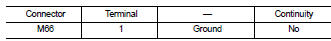
8.CHECK OPTICAL SENSOR SIGNAL FOR SHORT CIRCUIT
Check the continuity between the optical sensor harness connector and ground.
Does continuity exist? YES >> Repair the harnesses or connectors.
NO >> Replace BCM. Refer to BCS-96, "Removal and Installation"
 Turn signal lamp circuit
Description
The BCM monitors inputs from the combination switch to determine when to
activate the turn signals. The
BCM outputs voltage direction to the left and right turn signals during turn
...
 Headlamp (halogen)
Wiring Diagram - Coupe
Wiring Diagram - Sedan
...
Other materials:
P0448 evap canister vent control
valve
Description
The EVAP canister vent control valve is located on the EVAP canister
and is used to seal the canister vent.
This solenoid valve responds to signals from the ECM. When the
ECM sends an ON signal, the coil in the solenoid valve is energized.
A plunger will then move to seal the ca ...
Can communication circuit
Diagnosis Procedure
INSPECTION PROCEDURE
1.CONNECTOR INSPECTION
1. Turn the ignition switch OFF.
2. Disconnect the battery cable from the negative terminal.
3. Disconnect all the unit connectors on CAN communication system.
4. Check terminals and connectors for damage, bend and loose con ...
Camera on signal circuit (sedan)
Description
When the selector lever is placed in the R position, the rear view camera
control unit sends a camera ON signal
to the rear view camera.
Diagnosis Procedure
1.CHECK CAMERA ON SIGNAL CIRCUIT CONTINUITY
1. Turn ignition switch OFF.
2. Disconnect rear view camera control unit con ...
