Nissan Altima (L32) 2007-2012 Service Manual: Basic inspection
DIAGNOSIS AND REPAIR WORKFLOW
Work Flow
OVERALL SEQUENCE
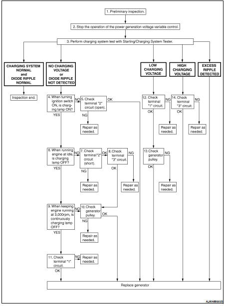
DETAILED FLOW
NOTE: To ensure a complete and thorough diagnosis, the battery, starter and generator test segments must be done as a set from start to finish.
1.PRELIMINARY INSPECTION
Perform the preliminary inspection. Refer to CHG-7, "Inspection Procedure".
>> GO TO 2
2.DISABLE THE POWER GENERATION VOLTAGE VARIABLE CONTROL SYSTEM
Disable the power generation voltage variable control with either of the following procedures.
• After selecting “ENGINE” on the “SELECT SYSTEM” screen of CONSULT-III, set the “ALTERNATOR DUTY” value to 0 % by selecting “ALTERNATOR DUTY” with “Active Test”. Continue “Active Test” until the end of inspection. (When the DUTY value is 0 or 100 %, the normal power generation is performed according to the characteristic of the IC regulator of the generator.) • Turn the ignition switch OFF, disconnect the battery current sensor connector and leave it disconnected during the course of the test.
NOTE: Running the engine with the battery current sensor disconnected will cause DTC's (P1550-P1554) to set.
After finishing the inspection, connect the battery current sensor connector and erase the self-diagnostic results history of the engine using CONSULT-III.
>> GO TO 3
3.DIAGNOSIS WITH STARTING/CHARGING SYSTEM TESTER
Perform the charging system test using Starting/Charging System Tester (J-44373). For details and operating instructions, refer to Technical Service Bulletin.
Test result
CHARGING SYSTEM NOMAL>>Charging system is normal and will also show “DIODE RIPPLE” test result.
NO CHARGING VOLTAGE>>GO TO 4
LOW CHARGING VOLTAGE>>GO TO 12
HIGH CHARGING VOLTAGE>>GO TO 14
HIGH CHARGING VOLTAGE>>GO TO 14 DIODE RIPPLE NORMAL>>Diode ripple is OK and will also show “CHARGING VOLTAGE” test result.
EXCESS RIPPLE DETECTED>>Replace the generator. Perform “DIODE RIPPLE” test again using Starting/ Charging System Tester (J-44373) to confirm repair.
DIODE RIPPLE NOT DETECTED>>GO TO 4
4.INSPECTION WITH CHARGE WARNING LAMP (IGNITION SWITCH IS ON)
Turn the ignition switch ON.
Does the charge warning lamp illuminate? YES >> GO TO 6
NO >> GO TO 5
5.TERMINAL“2” (OPEN) CIRCUIT INSPECTION
Check terminal “2” circuit for open circuits. Refer to CHG-11, "Diagnosis Procedure".
Is the terminal “2” circuit normal? YES >> Replace generator. Refer to CHG-27, "Removal and Installation".
NO >> Repair as needed.
6.INSPECTION WITH CHARGE WARNING LAMP (IDLING)
Start the engine and run it at idle.
Does the charge warning lamp turn OFF? YES >> GO TO 9
NO >> GO TO 7
7.TERMINAL “2”(SHORT) CIRCUIT INSPECTION
Check terminal “2” circuit for short to ground. Refer to CHG-11, "Diagnosis Procedure".
Is the terminal “2” circuit normal?
YES >> GO TO 8
NO >> Repair as needed.
8.TERMINAL“3” CIRCUIT INSPECTION
Check terminal “3” circuit. Refer to CHG-12, "Diagnosis Procedure".
Is the terminal “3” circuit normal? YES >> GO TO 10
NO >> Repair as needed.
9.INSPECTION WITH CHARGE WARNING LAMP (ENGINE AT 3,000 RPM)
Increase and maintain the engine speed at 3,000 rpm.
Does the charge warning lamp remain off? YES >> GO TO 11
NO >> GO TO 10
10.INSPECTION OF GENERATOR PULLEY
Check generator pulley. Refer to CHG-29, "Inspection".
Is generator pulley normal? YES >> Replace generator. Refer to CHG-27, "Removal and Installation".
NO >> Repair as needed.
11.TERMINAL “1” CIRCUIT INSPECTION
Check terminal “1””circuit. Refer to CHG-10, "Diagnosis Procedure".
Is terminal “1” circuit normal? YES >> Replace generator. Refer to CHG-27, "Removal and Installation".
NO >> Repair as needed.
12.TERMINAL “1” CIRCUIT INSPECTION
Check terminal “1” circuit. Refer to CHG-10, "Diagnosis Procedure".
Is terminal “1” circuit normal? YES >> GO TO 13
NO >> Repair as needed.
13.INSPECTION OF GENERATOR PULLEY
Check generator pulley. Refer to CHG-29, "Inspection".
Is generator pulley normal? YES >> Replace generator. Refer to CHG-27, "Removal and Installation".
NO >> Repair as needed.
14.TERMINAL “3” CIRCUIT INSPECTION
Check terminal “3” circuit. Refer to CHG-12, "Diagnosis Procedure".
Is the terminal “3” circuit normal? YES >> Replace generator. Refer to CHG-27, "Removal and Installation".
NO >> Repair as needed.
 Charging system
...

Other materials:
Key slot illumination
Description
Blinks when keyfob insertion is required.
Component Function Check
1.CHECK FUNCTION
Check key slot illumination (“KEY SLOT ILLUMI”) Active Test mode.
Is the inspection result normal?
YES >> Key slot function is OK.
NO >> Refer to SEC-505, "Diagnosis Pr ...
Engine control system
System Diagram
System Description
ECM performs various controls such as fuel injection control and ignition
timing control.
Component Parts Location
1. Intake valve timing control solenoid
valve
2. Ignition coil (with power transistor)
and spark plug
3. Knock sensor,
Crankshaft posi ...
On-vehicle repair
ACCELERATOR CONTROL SYSTEM
Exploded View
1. Accelerator pedal and accelerator
position sensor assembly.
2. Locating pins
Removal and Installation
REMOVAL
1. Disconnect the battery negative terminal.
2. Disconnect the accelerator position sensor electrical connector.
3. Remove the t ...
