Nissan Altima (L32) 2007-2012 Service Manual: Door switch
Description
Detects door open/close condition.
Component Function Check
1.CHECK FUNCTION

Check door switches DOOR SW-DR, DOOR SW-AS in Data Monitor mode with CONSULT-III.

Is the inspection result normal? YES >> Door switch is OK.
NO >> Refer to RF-17, "Diagnosis Procedure".
Diagnosis Procedure
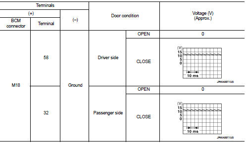
1.CHECK DOOR SWITCH INPUT SIGNAL
1. Turn ignition switch OFF.
2. Check signal between BCM connector and ground with oscilloscope.
Is the inspection result normal? YES >> GO TO 4
NO >> GO TO 2
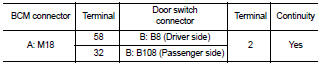
2.CHECK DOOR SWITCH CIRCUIT
1. Disconnect BCM connector.
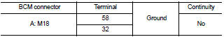
2. Check continuity between BCM connector and door switch connector.
3. Check continuity between BCM connector and ground.
Is the inspection result normal? YES >> GO TO 3
NO >> Repair or replace harness between BCM and door switch.
3.CHECK DOOR SWITCH
Refer to RF-19, "Component Inspection".
Is the inspection result normal? YES >> GO TO 4
NO >> Replace malfunctioning door switch.
4.CHECK INTERMITTENT INCIDENT
Refer to GI-42, "Intermittent Incident".
>> Inspection End.
Component Inspection
1.CHECK DOOR SWITCH
1. Turn ignition switch OFF.
2. Disconnect door switch connector.
3. Check door switch.
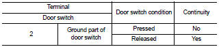
Is the inspection result normal? YES >> Inspection End.
NO >> Replace malfunctioning door switch.
 Power supply and ground circuit
SUNROOF MOTOR ASSEMBLY
Description
• BCM supplies power.
• CPU is integrated in sunroof motor assembly.
• Tilts up/down & slides open/close by sunroof switch operation.
• ...
 ECU diagnosis
...
Other materials:
Basic inspection
DIAGNOSIS AND REPAIR WORKFLOW
Work Flow
OVERALL SEQUENCE
DETAILED FLOW
NOTE:
To ensure a complete and thorough diagnosis, the battery, starter motor and
alternator test segments must be
done as a set from start to finish.
1.DIAGNOSIS WITH STARTING/CHARGING SYSTEM TESTER
Perform the start ...
Exhaust manifold and three way
catalyst
Removal and Installation
1. Exhaust manifold heat shield (RH)
2. Air fuel ratio (A/F) sensor 1 (bank 1)
3. Exhaust manifold (RH)
4. Gaskets
5. Heated oxygen sensor 2 (bank 1)
6. Three way catalyst (manifold) (bank
1)
7. Three way catalyst (manifold) (bank
2)
8. Heated oxygen sensor 2 (ba ...
Parking lamp circuit
Description
The IPDM E/R (intelligent power distribution module engine room) controls the
tail lamp relay based on inputs
from the BCM over the CAN communication lines. When the tail lamp relay is
energized, power flows through
fuses 46 and 47, located in the IPDM E/R. Power then flows to th ...
