Nissan Altima 2007-2012 Service Manual: Power consumption control system
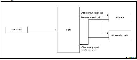
System Diagram
System Description
OUTLINE
• BCM incorporates a power saving control function that reduces the power consumption according to the vehicle status.
• BCM switches the status (control mode) by itself with the power saving control function. It performs the sleep request to each unit (IPDM E/R and combination meter) that operates with the ignition switch OFF.
Normal mode (wake-up)
- CAN communication is normally performed with other units
- Each control with BCM is operating properly
CAN communication sleep mode (CAN sleep)
- CAN transmission is stopped
- Control with BCM only is operating
Low power consumption mode (BCM sleep)
- Low power consumption control is active
- CAN transmission is stopped
LOW POWER CONSUMPTION CONTROL WITH BCM
BCM reduces the power consumption with the following operation in the low power consumption mode.
• The reading interval of the each switches changes from 10 ms interval to 60 ms interval.
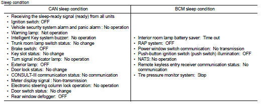
Sleep mode activation
• BCM receives the sleep-ready signal (ready) from IPDM E/R and combination meter via CAN communication.
• BCM transmits the sleep wake up signal (sleep) to each unit when all of the CAN sleep conditions are fulfilled.
• Each unit stops the transmission of CAN communication with the sleep wakeup signal. BCM is in CAN communication sleep mode.
• BCM is in the low power consumption mode and perform the low power consumption control when all of the BCM sleep conditions are fulfilled with CAN sleep condition.
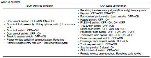
Wake-up operation
• BCM changes from the low power consumption mode to the CAN communication sleep mode when the any of the BCM wake-up conditions is fulfilled. Only the control with BCM is activated.
• BCM transmits the sleep wake up signal (wake up) to each unit when any of the CAN wake-up conditions is fulfilled. It changes from the low power consumption mode or the CAN communication sleep mode to the normal mode.
• Each unit starts the transmission of CAN communication with the sleep wake up signal. In addition, the combination meter transmits the wake up signal to BCM via CAN communication to report the CAN communication start.
Component Parts Location
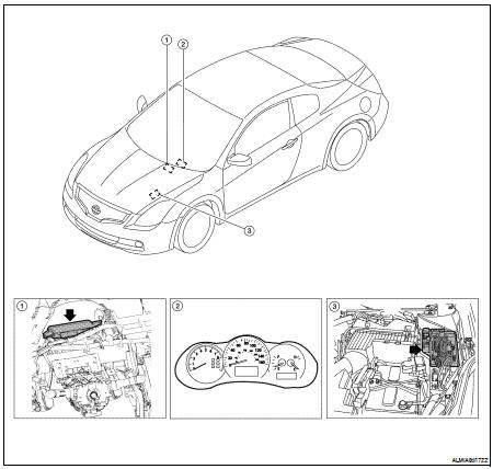
1. BCM M16, M17, M18, M19, M20, M21 (view with instrument panel removed) (coupe shown, sedan similar)
2. Combination meter M24
3. IPDM E/R E16, E17, E18, E200, E201, F10
 Signal buffer system
System Diagram
System Description
OUTLINE
BCM has the signal transmission function that outputs/transmits each
input/received signal to each unit.
Signal transmission function list
...

Other materials:
P0171, P0174 Fuel injection system function
DTC Logic
DTC DETECTION LOGIC
With the Air/Fuel Mixture Ratio Self-Learning Control, the actual mixture
ratio can be brought closely to the
theoretical mixture ratio based on the mixture ratio feedback signal from A/F
sensor 1. The ECM calculates
the necessary compensation to correct the off ...
B1049 – B1052, B1054 – B1057 driver airbag
module
Description
DTC B1049 – B1052, B1054 – B1057 DRIVER AIRBAG MODULE
The driver air bag module is dual stage and wired to the air bag diagnosis
sensor unit through the spiral cable.
The air bag diagnosis sensor unit will monitor for opens and shorts in detected
lines to the driver air bag ...
Power consumption control system
System Diagram
System Description
OUTLINE
• BCM incorporates a power saving control function that reduces the power
consumption according to the
vehicle status.
• BCM switches the status (control mode) by itself with the power saving control
function. It performs the sleep
request ...
