Nissan Altima 2007-2012 Service Manual: Can communication circuit
Diagnosis Procedure
INSPECTION PROCEDURE
1.CONNECTOR INSPECTION
1. Turn the ignition switch OFF.
2. Disconnect the battery cable from the negative terminal.
3. Disconnect all the unit connectors on CAN communication system.
4. Check terminals and connectors for damage, bend and loose connection.
Is the inspection result normal? YES >> GO TO 2.
NO >> Repair the terminal and connector.
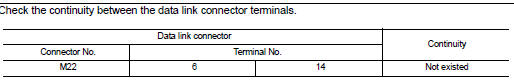
2.CHECK HARNESS CONTINUITY (SHORT CIRCUIT)
Check the continuity between the data link connector terminals.
Is the inspection result normal? YES >> GO TO 3.
NO >> Check the harness and repair the root cause.
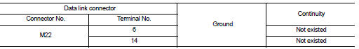
3.CHECK HARNESS CONTINUITY (SHORT CIRCUIT)
Check the continuity between the data link connector and the ground.
Is the inspection result normal? YES >> GO TO 4.
NO >> Check the harness and repair the root cause.
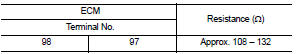
4.CHECK ECM AND IPDM E/R TERMINATION CIRCUIT
1. Remove the ECM and the IPDM E/R.
2. Check the resistance between the ECM terminals.
3. Check the resistance between the IPDM E/R terminals.
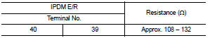
Is the measurement value within the specification? YES >> GO TO 5.
NO >> Replace the ECM and/or the IPDM E/R.
5.CHECK SYMPTOM
Connect all the connectors. Check if the symptoms described in the “Symptom (Results from interview with customer)” are reproduced.
Inspection result Reproduced>>GO TO 6.
Non-reproduced>>Start the diagnosis again. Follow the trouble diagnosis procedure when past error is detected.
6.CHECK UNIT REPRODUCTION
Perform the reproduction test as per the following procedure for each unit.
1. Turn the ignition switch OFF.
2. Disconnect the battery cable from the negative terminal.
3. Disconnect one of the unit connectors of CAN communication system.
NOTE: ECM and IPDM E/R have a termination circuit. Check other units first.
4. Connect the battery cable to the negative terminal. Check if the symptoms described in the “Symptom (Results from interview with customer)” are reproduced.
NOTE: Although unit-related error symptoms occur, do not confuse them with other symptoms.
Inspection result
Reproduced>>Connect the connector. Check other units as per the above procedure.
Non-reproduced>>Replace the unit whose connector was disconnected.
 IPDM-E branch line circuit
Diagnosis Procedure
INSPECTION PROCEDURE
1.CHECK CONNECTOR
1. Turn the ignition switch OFF.
2. Disconnect the battery cable from the negative terminal.
3. Check the terminals and connectors o ...
 Lan system can system (type 9)
COMPONENT DIAGNOSIS ...
Other materials:
Bose speaker AMP
Diagnosis Procedure
1.CHECK FUSE
Check for blown fuses.
Are the fuses OK?
YES >> GO TO 2
NO >> Be sure to eliminate cause of malfunction before installing new fuse.
2.CHECK POWER SUPPLY CIRCUIT
1. Turn ignition switch OFF.
2. Disconnect BOSE speaker amp connector.
3. Chec ...
Service data and specifications(SDS)
Wheel Alignment (Unladen*)
Fuel, radiator coolant and engine
oil full. Spare tire, jack, hand tools and mats in designated positions.
Fuel,
radiator coolant and engine oil full. Spare tire, jack, hand tools and mats in
designated positions.
Ball Joint
Wheelarch Height (Unladen*1) ...
Satellite radio tuner
Removal and Installation - Coupe
REMOVAL
1. Disconnect the battery negative terminal.
2. Remove the trunk floor carpet and spare tire cover. Refer to INT-23, "Removal
and Installation".
3. Remove the LH trunk floor spacer.
4. Remove the satellite radio tuner assembly nuts (B), ...
