Nissan Altima (L32) 2007-2012 Service Manual: ABS branch line circuit
Diagnosis Procedure
INSPECTION PROCEDURE
1.CHECK CONNECTOR
1. Turn the ignition switch OFF.
2. Disconnect the battery cable from the negative terminal.
3. Check the terminals and connectors of the ABS actuator and electric unit (control unit) for damage, bend and loose connection (unit side and connector side).
Is the inspection result normal? YES >> GO TO 2.
NO >> Repair the terminal and connector.
2.CHECK HARNESS FOR OPEN CIRCUIT
1. Disconnect the connector of ABS actuator and electric unit (control unit).
2. Check the resistance between the ABS actuator and electric unit (control unit) harness connector terminals.
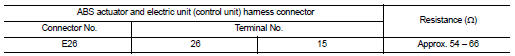
Is the measurement value within the specification? YES >> GO TO 3.
NO >> Repair the ABS actuator and electric unit (control unit) branch line.
3.CHECK POWER SUPPLY AND GROUND CIRCUIT
Check the power supply and the ground circuit of the ABS actuator and electric unit (control unit). Refer to the following.
• Models with ABS: BRC-41, "Wiring Diagram - Coupe" or BRC-46, "Wiring Diagram - Sedan" • Models with TCS: BRC-109, "Wiring Diagram - Coupe" or BRC-115, "Wiring Diagram - Sedan" • Models with VDC: BRC-207, "Wiring Diagram - Coupe" or BRC-215, "Wiring Diagram - Sedan" Is the inspection result normal? YES (Present error)>>Replace the ABS actuator and electric unit (control unit). Refer to the following.
• Models with ABS: BRC-66, "Exploded View" • Models with TCS: BRC-137, "Exploded View" • Models with VDC: BRC-239, "Exploded View" YES (Past error)>>Error was detected in the ABS actuator and electric unit (control unit) branch line.
NO >> Repair the power supply and the ground circuit.
 STRG branch line circuit
Diagnosis Procedure
INSPECTION PROCEDURE
1.CHECK CONNECTOR
1. Turn the ignition switch OFF.
2. Disconnect the battery cable from the negative terminal.
3. Check the terminals and connectors o ...
 IPDM-E branch line circuit
Diagnosis Procedure
INSPECTION PROCEDURE
1.CHECK CONNECTOR
1. Turn the ignition switch OFF.
2. Disconnect the battery cable from the negative terminal.
3. Check the terminals and connectors o ...
Other materials:
M&A branch line circuit
Diagnosis Procedure
INSPECTION PROCEDURE
1.CHECK CONNECTOR
1. Turn the ignition switch OFF.
2. Disconnect the battery cable from the negative terminal.
3. Check the terminals and connectors of the combination meter for damage, bend
and loose connection
(unit side and connector side).
...
Front seat
Exploded View
DRIVER'S SEAT
1. Headrest
2. Headrest holder (locked)
3. Headrest holder (free)
4. Seatback board
5. Seatback assembly
6. Slide cover
7. Seat belt buckle
8. Seat harness
9. Seat cushion heater unit
10. Seat cushion
11. Seat trim
12. Front leg covers
13. Seat cushion fr ...
Child safety
WARNING
Do not allow children to play with the seat
belts. Most seating positions are
equipped with Automatic Locking Retractor
(ALR) mode seat belts. If the seat belt
becomes wrapped around a child’s neck
with the ALR mode activated, the child can
be seriously injured or killed if the seat ...
