Nissan Altima (L32) 2007-2012 Service Manual: Front wiper and washer system
System Diagram
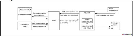
System Description
OUTLINE
The front wiper is controlled by each function of BCM and IPDM E/R.
Control by BCM
• Combination switch reading function
• Front wiper control function
Control by IPDM E/R
• Front wiper control function
• Relay control function
FRONT WIPER BASIC OPERATION
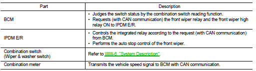
• BCM detects the combination switch condition by the combination switch reading function.
• BCM transmits the front wiper request signal to IPDM E/R with CAN communication depending on each operating condition of the front wiper.
• IPDM E/R turns ON/OFF the integrated front wiper relay and the front wiper high relay according to the front wiper request signal. IPDM E/R provides the power supply to operate the front wiper HI/LO operation.
FRONT WIPER LO OPERATION
• BCM transmits the front wiper request signal (LO) to IPDM E/R with CAN communication according to the front wiper LO operating condition.
Front wiper LO operating condition
- Ignition switch ON
- Front wiper switch LO or front wiper switch MIST (while pressing)
• IPDM E/R turns ON the integrated front wiper relay according to the front wiper request signal (LO).
FRONT WIPER HI OPERATION
• BCM transmits the front wiper request signal (HI) to IPDM E/R with CAN communication according to the front wiper HI operating condition.
Front wiper HI operating condition
- Ignition switch ON
- Front wiper switch HI
• IPDM E/R turns ON the integrated front wiper relay and the front wiper high relay according to the front wiper request signal (HI).
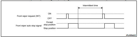
FRONT WIPER INT OPERATION
• BCM transmits the front wiper request signal (INT) to IPDM E/R with CAN communication depending on the front wiper INT operating condition and intermittent operation delay interval according to the wiper intermittent dial position.
Front wiper INT operating condition
- Ignition switch ON
- Front wiper switch INT
• IPDM E/R turns ON the integrated front wiper relay so that the front wiper is operated only once according to the front wiper request signal (INT).
• BCM detects stop position/except stop position of the front wiper motor according to the front wiper auto stop signal received from IPDM E/R with CAN communication.
• BCM transmits the front wiper request signal (INT) again after the intermittent operation delay interval.
NOTE: Front wiper intermittent operation can be set to the operation with vehicle speed by CONSULT-III. Refer to BCS-26, "WIPER : CONSULT - III Function".
Front wiper intermittent operation with vehicle speed
• BCM calculates the intermittent operation delay interval from the following
- Vehicle speed signal (received from the combination meter with CAN communication) - Wiper intermittent dial position
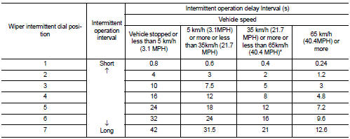
*: When without vehicle speed setting
FRONT WIPER AUTO STOP OPERATION
• BCM stops transmitting the front wiper request signal when the front wiper switch is turned OFF.
• IPDM E/R detects the front wiper auto stop signal from the front wiper motor and detects the front wiper motor position (stop position/except stop position).
• When the front wiper request signal is stopped, IPDM E/R turns ON the front wiper relay until the front wiper motor returns to the stop position.
NOTE: • BCM stops the transmitting of the front wiper request signal when the ignition switch OFF.
• IPDM E/R turns the front wiper relay OFF when the ignition switch OFF.
FRONT WIPER OPERATION LINKED WITH WASHER
• BCM transmits the front wiper request signal (LO) to IPDM E/R with CAN communication according to the washer linked operating condition of the front wiper.
• BCM transmits the front wiper request signal (LO) so that the front wiper operates approximately 2 times when the front washer switch OFF is detected.
Washer linked operating condition of front wiper
- Ignition switch ON
- Ignition switch ON
• IPDM E/R turns ON the integrated front wiper relay according to the front wiper request signal (LO).
• The front washer motor is grounded through the combination switch when the front washer switch is ON.
FRONT WIPER FAIL−SAFE OPERATION
When the front wiper auto stop circuit is malfunctioning, IPDM E/R performs the fail-safe function. Refer to PCS-43, "Fail Safe".
Component Parts Location
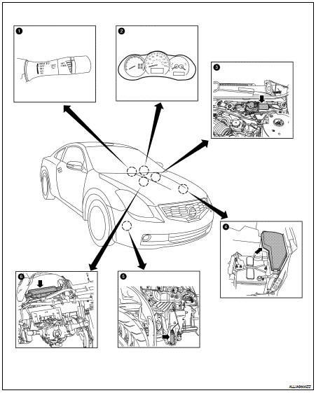
1. Combination switch M28 (wiper switch) (coupe shown, sedan similar)
2. Combination meter M24
3. Front wiper motor E25
4. IPDM E/R E17, E18, E200
5. Front washer motor E226
6. BCM M16, M17, M18, M19 (view with instrument panel removed)
Component Description
 Function diagnosis
 Diagnosis system (BCM)
Other materials:
Multiport fuel injection system
System Diagram
System Description
INPUT/OUTPUT SIGNAL CHART
*1: This sensor is not used to control the engine system under normal
conditions.
*2: This signal is sent to the ECM via the CAN communication line.
*3: ECM determines the start signal status by the signals of engine speed an ...
License plate lamp
Bulb Replacement
REMOVAL
1. Position trunk lid finisher aside.
2. Turn license plate lamp bulb socket counterclockwise to unlock
and remove.
3. Pull license plate lamp bulb to remove from socket.
INSTALLATION
Installation is in the reverse order of removal.
Removal and Installation
...
Diagnosis system (audio unit)
Diagnosis Description
Self-diagnosis mode can check the following items.
• Audio unit hardware/software versions
• Continuity of each speaker channel
• Continuity of each audio unit switch
OPERATION PROCEDURE
1. Turn ignition switch to the ACC position.
2. Turn the audio unit off.
...
