Nissan Altima 2007-2012 Service Manual: IPDM-E branch line circuit
Diagnosis Procedure
INSPECTION PROCEDURE
1.CHECK CONNECTOR
1. Turn the ignition switch OFF.
2. Disconnect the battery cable from the negative terminal.
3. Check the terminals and connectors of the IPDM E/R for damage, bend and loose connection (unit side and connector side).
Is the inspection result normal? YES >> GO TO 2.
NO >> Repair the terminal and connector.
2.CHECK HARNESS FOR OPEN CIRCUIT
1. Disconnect the connector of IPDM E/R.
2. Check the resistance between the IPDM E/R harness connector terminals.
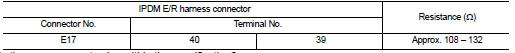
Is the measurement value within the specification? YES >> GO TO 3.
NO >> Repair the IPDM E/R branch line.
3.CHECK POWER SUPPLY AND GROUND CIRCUIT
Check the power supply and the ground circuit of the IPDM E/R. Refer to PCS-23, "Diagnosis Procedure" .
Is the inspection result normal? YES (Present error)>>Replace the IPDM E/R. Refer to PCS-48, "Removal and Installation".
YES (Past error)>>Error was detected in the IPDM E/R branch line.
NO >> Repair the power supply and the ground circuit.
 ABS branch line circuit
Diagnosis Procedure
INSPECTION PROCEDURE
1.CHECK CONNECTOR
1. Turn the ignition switch OFF.
2. Disconnect the battery cable from the negative terminal.
3. Check the terminals and connectors ...
 Can communication circuit
Diagnosis Procedure
INSPECTION PROCEDURE
1.CONNECTOR INSPECTION
1. Turn the ignition switch OFF.
2. Disconnect the battery cable from the negative terminal.
3. Disconnect all the unit connect ...
Other materials:
Rear seat
Exploded View
BENCH SEAT
1. Rear seat side bolster assembly LH
2. Rear seatback latch mount
3. Rear seat side bolster assembly RH
4. Rear seatback latch
5. Rear seatback trim panel
6. Seat belt guide
7. Rear seatback pad RH
8. Rear seatback pad LH
9. Rear seatback pad trim RH
10. Rear ...
ABS branch line circuit
Diagnosis Procedure
INSPECTION PROCEDURE
1.CHECK CONNECTOR
1. Turn the ignition switch OFF.
2. Disconnect the battery cable from the negative terminal.
3. Check the terminals and connectors of the ABS actuator and electric unit
(control unit) for damage, bend
and loose connection (unit ...
AV control unit
Diagnosis Procedure
1.CHECK FUSE
Check that the following fuses of the AV control unit are not blown.
Are the fuses OK?
YES >> GO TO 2
NO >> Be sure to eliminate cause of malfunction before installing new fuse.
2.CHECK POWER SUPPLY CIRCUIT
Check voltage between AV control unit h ...
