Nissan Altima (L32) 2007-2012 Service Manual: Basic inspection
DIAGNOSIS AND REPAIR WORKFLOW
Work Flow
OVERALL SEQUENCE
DETAILED FLOW
1. GET INFORMATION FOR SYMPTOM
Get the detailed information from the customer about the symptom (the condition and the environment when the incident/malfunction occurred).
>> GO TO 2
2. CHECK DTC
1. Check DTC.
2. Perform the following procedure if DTC is displayed.
- Record DTC and freeze frame data.
- Erase DTC.
- Study the relationship between the cause detected by DTC and the symptom described by the customer.
3. Check related service bulletins for information.
Is any symptom described and any DTC detected? Symptom is described, DTC is displayed>>GO TO 3
Symptom is described, DTC is not displayed>>GO TO 4
Symptom is not described, DTC is displayed>>GO TO 5
3. CONFIRM THE SYMPTOM
Confirm the symptom described by the customer.
Connect CONSULT-III to the vehicle in “DATA MONITOR” mode and check real time diagnosis results.
Verify relation between the symptom and the condition when the symptom is detected.
>> GO TO 5
4. CONFIRM THE SYMPTOM
Confirm the symptom described by the customer.
Connect CONSULT-III to the vehicle in “DATA MONITOR ” mode and check real time diagnosis results.
Verify relation between the symptom and the condition when the symptom is detected.
>> GO TO 6
5. PERFORM DTC CONFIRMATION PROCEDURE
Perform DTC Confirmation Procedure for the displayed DTC, and then check that DTC is detected again.
At this time, always connect CONSULT-III to the vehicle, and check diagnostic results in real time.
If two or more DTCs are detected, refer to BCS-90, "DTC Inspection Priority Chart" and determine trouble diagnosis order.
NOTE: • Freeze frame data is useful if the DTC is not detected.
• Perform Component Function Check if DTC Confirmation Procedure is not included in Service Manual. This simplified check procedure is an effective alternative though DTC cannot be detected during this check.
If the result of Component Function Check is NG, it is the same as the detection of DTC by DTC Confirmation Procedure.
Is DTC detected? YES >> GO TO 8
NO >> Refer to BCS-91, "DTC Index".
6. PERFORM BASIC INSPECTION
Perform BCS-3, "Work Flow".
Inspection End>>GO TO 7
7. DETECT MALFUNCTIONING SYSTEM BY SYMPTOM TABLE
Detect malfunctioning system according to BCS-8, "System Description" based on the confirmed symptom in step 4, and determine the trouble diagnosis order based on possible causes and symptom.
>> GO TO 8
8. DETECT MALFUNCTIONING PART BY DIAGNOSTIC PROCEDURE
Inspect according to Diagnostic Procedure of the system.
NOTE: The Diagnostic Procedure described based on open circuit inspection. A short circuit inspection is also required for the circuit check in the Diagnostic Procedure.
Is malfunctioning part detected? YES >> GO TO 9
NO >> Check voltage of related BCM terminals using CONSULT-III.
9. REPAIR OR REPLACE THE MALFUNCTIONING PART
1. Repair or replace the malfunctioning part.
2. Reconnect parts or connectors disconnected during Diagnostic Procedure again after repair and replacement.
3. Check DTC. If DTC is displayed, erase it.
>> GO TO 10
10. FINAL CHECK
When DTC was detected in step 2, perform DTC Confirmation Procedure or Component Function Check again, and then check that the malfunction has been repaired.
When symptom was described from the customer, refer to confirmed symptom in step 3 or 4, and check that the symptom is not detected.
Does the symptom reappear? YES (DTC is detected)>>GO TO 8
YES (Symptom remains)>>GO TO 6
NO >> Inspection End.
ADDITIONAL SERVICE WHEN REPLACING CONTROL UNIT
Description
BEFORE REPLACEMENT
When replacing BCM, save or print current vehicle specification with CONSULT-III configuration before replacement.
NOTE: If “READ CONFIGURATION” can not be used, use the “WRITE CONFIGURATION - Manual selection” after replacing BCM.
AFTER REPLACEMENT
CAUTION: • When replacing BCM, you must perform “WRITE CONFIGURATION” with CONSULT-III.
- Complete the procedure of “WRITE CONFIGURATION” in order.
- If you set incorrect “WRITE CONFIGURATION”, incidents might occur.
- Configuration is different for each vehicle model. Confirm configuration of each vehicle model.
• When replacing BCM, perform the system initialization (NATS).
Special Repair Requirement
1. SAVING VEHICLE SPECIFICATION

Perform “READ CONFIGURATION” to save or print current vehicle specification. Refer to BCS-6, "CONFIGURATION (BCM) : Description".
NOTE: If “READ CONFIGURATION” cannot be used, use the “WRITE CONFIGURATION - Manual selection” after replacing BCM.
>> GO TO 2
2. REPLACE BCM
Replace BCM. Refer to BCS-96, "Removal and Installation".
>> GO TO 3
3. WRITING VEHICLE SPECIFICATION

Perform “WRITE CONFIGURATION - Config file” or “WRITE CONFIGURATION - Manual selection” to write vehicle specification. Refer to BCS-6, "CONFIGURATION (BCM) : Special Repair Requirement".
>> GO TO 4
4. INITIALIZE BCM (NATS)
Perform BCM initialization (NATS). Refer to CONSULT-III Operation Manual NATS-IVIS/NVIS.
>> Inspection End.
CONFIGURATION (BCM)
Description
Vehicle specification needs to be written with CONSULT-III because it is not written after replacing BCM.
Configuration has three functions as follows
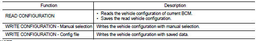
NOTE: Manual setting item: Items which need selection by vehicle specifications Automatic setting item: Items which are written in automatically (Setting cannot be changed) CAUTION: • When replacing BCM, you must perform “WRITE CONFIGURATION” with CONSULT-III.
• Complete the procedure of “WRITE CONFIGURATION” in order.
• If you set incorrect “WRITE CONFIGURATION”, incidents might occur.
• Configuration is different for each vehicle model. Confirm configuration of each vehicle model.
• Never perform “WRITE CONFIGURATION” except for new BCM.
Special Repair Requirement
1. WRITING MODE SELECTION

Select “CONFIGURATION” of BCM.
When writing saved data>>GO TO 2
When writing manually>>GO TO 3
2. PERFORM “WRITE CONFIGURATION - CONFIG FILE”

Perform “WRITE CONFIGURATION - Config File”.
>> Inspection End.
3. PERFORM “WRITE CONFIGURATION - MANUAL SELECTION”

1. Select "WRITE CONFIGURATION - Manual selection".
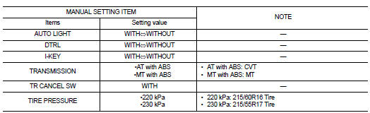
2. Identify the correct model and configuration list. Refer to BCS-7, "CONFIGURATION (BCM) : Configuration list".
3. Confirm and/or change setting value for each item.
4. Select "Setting change".
CAUTION: Make sure to select “Setting change” even if the indicated configuration of brand new BCM is same as the desirable configuration. If not, configuration which is set automatically by selecting vehicle model cannot be memorized. 5. When "COMMAND FINISHED", select "END".
>> GO TO 4
4. OPERATION CHECK
Confirm that each function controlled by BCM operates normally.
>> Inspection End.
Configuration list


Other materials:
Precaution
Supplemental Restraint System (SRS) "AIR BAG"
and "SEAT BELT PRE-TENSIONER"
The Supplemental Restraint System such as “AIR BAG” and “SEAT BELT PRE-TENSIONER”,
used along
with a front seat belt, helps to reduce the risk or severity of injury to the
driver and front ...
Rear LH
Description
Door glass moves UP/DOWN by receiving the signal from main power window and
door lock/unlock switch or
rear power window switch LH.
Component Function Check
1. CHECK REAR POWER WINDOW MOTOR LH CIRCUIT
Does rear power window motor LH operate with main power window and door
...
AV control unit
Diagnosis Procedure
1.CHECK FUSE
Check that the following fuses of the AV control unit are not blown.
Are the fuses OK?
YES >> GO TO 2
NO >> Be sure to eliminate cause of malfunction before installing new fuse.
2.CHECK POWER SUPPLY CIRCUIT
Check voltage between AV control unit ...
