Nissan Altima (L32) 2007-2012 Service Manual: BCM branch line circuit
Diagnosis Procedure
INSPECTION PROCEDURE
1.CHECK CONNECTOR
1. Turn the ignition switch OFF.
2. Disconnect the battery cable from the negative terminal.
3. Check the terminals and connectors of the BCM for damage, bend and loose connection (unit side and connector side).
Is the inspection result normal? YES >> GO TO 2.
NO >> Repair the terminal and connector.
2.CHECK HARNESS FOR OPEN CIRCUIT
1. Disconnect the connector of BCM.
2. Check the resistance between the BCM harness connector terminals.
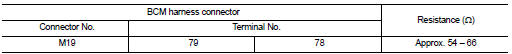
Is the measurement value within the specification? YES >> GO TO 3.
NO >> Repair the BCM branch line.
3.CHECK POWER SUPPLY AND GROUND CIRCUIT
Check the power supply and the ground circuit of the BCM. Refer to BCS-42, "Diagnosis Procedure".
Is the inspection result normal? YES (Present error)>>Replace the BCM. Refer to BCS-96, "Removal and Installation".
YES (Past error)>>Error was detected in the BCM branch line.
NO >> Repair the power supply and the ground circuit.
 A-BAG branch line circuit
Diagnosis Procedure
1.CHECK AIR BAG DIAGNOSIS SENSOR UNIT
Check the air bag diagnosis sensor unit. Refer to SRC-3, "Work Flow".
Is the inspection result normal?
YES >> Replace t ...
 DLC branch line circuit
Diagnosis Procedure
INSPECTION PROCEDURE
1.CHECK CONNECTOR
1. Turn the ignition switch OFF.
2. Disconnect the battery cable from the negative terminal.
3. Check the terminals and connectors o ...
Other materials:
U0101 Can comm circuit
Description
CAN (Controller Area Network) is a serial communication line for real time
application. It is an on-vehicle multiplex
communication line with high data communication speed and excellent error
detection ability. Many electronic
control units are equipped onto a vehicle, and each co ...
Making a call
To make a call from a phone connected to the
vehicle’s Bluetooth® Hands-Free Phone System:
1. Press the button on the
steering
wheel.
2. The system will prompt you for a command.
Say “Call”.
3. Select one of the available voice commands
to continue:
● “(A Name)” — Spea ...
Removal and installation
TRANSAXLE ASSEMBLY
Exploded View
1. Rear gusset
2. Air breather hose
3. CVT fluid level gauge
4. CVT fluid charging pipe
5. O-ring
6. Copper washer
7. Fluid cooler tube
8. Transaxle assembly
A. Refer to TM-259, "Removal and
Installation".
Removal and Installation
REMOVAL
...
