Nissan Altima (L32) 2007-2012 Service Manual: Parking, license plate and tail lamps are not turned on
Description
The parking, license plate and tail lamps do not turn ON in with any lighting switch setting.
Diagnosis Procedure
1.COMBINATION SWITCH INSPECTION
Check the combination switch. Refer to BCS-10, "System Description".
Is the combination switch normal? YES >> GO TO 2
NO >> Repair or replace the malfunctioning part.
2.CHECK TAIL LAMP RELAY REQUEST SIGNAL INPUT

1. Select "TAIL & CLR REQ" of IPDM E/R DATA MONITOR item.
2. With operating the lighting switch, check the monitor status.
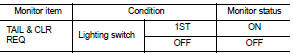
Is the item status normal? YES >> GO TO 3
NO >> Replace BCM. Refer to BCS-96, "Removal and Installation".
3.PARK LAMP CIRCUIT INSPECTION
Check the parking lamp circuit. Refer to EXL-48, "Description".
Is the tail lamp circuit normal? YES >> Replace IPDM E/R. Refer to PCS-48, "Removal and Installation".
NO >> Repair or replace the malfunctioning part.
 Both side headlamps (LO) are not
turned on
Both side headlamps (LO) are not
turned on
Description
The headlamps (both sides) do not turn ON in any lighting switch setting.
Diagnosis Procedure
1.CHECK COMBINATION SWITCH
Check the combination switch. Refer to BCS-10, "System De ...
 Both side front fog lamps are not
turned on
Both side front fog lamps are not
turned on
Description
The front fog lamps do not turn ON in any setting.
Diagnosis Procedure
1.COMBINATION SWITCH INSPECTION
Check the combination switch. Refer to BCS-10, "System Description".
...
Other materials:
Navigation system (sedan)
System Diagram
System Description
NOTE:
Refer to NAVI System Owner's Manual for system operation.
The navigation system periodically calculates the vehicle's current
position according to the following three signals: Travel distance of
the vehicle as determined by the vehicle speed sensor, t ...
Precaution
Precaution for Supplemental Restraint System
(SRS) "AIR BAG" and "SEAT BELT PRE-TENSIONER"
The Supplemental Restraint System such as “AIR BAG” and “SEAT BELT PRE-TENSIONER”,
used along
with a front seat belt, helps to reduce the risk or severity of injury to the
dr ...
CVT system
System Diagram
Component Parts Location - Coupe
1. Control device assembly (Manual
mode select switch and manual
mode position select switch)
2. Accelerator pedal position (APP)
sensor
3. Secondary speed sensor
4. CVT unit harness connector
5. TCM
6. Battery
7. Shift position indicato ...
