Nissan Altima (L32) 2007-2012 Service Manual: Main line between dlc and abs circuit
Diagnosis Procedure
INSPECTION PROCEDURE
1.CHECK CONNECTOR
1. Turn the ignition switch OFF.
2. Disconnect the battery cable from the negative terminal.
3. Check the following terminals and connectors for damage, bend and loose connection (connector side and harness side).
- Harness connector M1
- Harness connector E30
Is the inspection result normal? YES >> GO TO 2.
NO >> Repair the terminal and connector.
2.CHECK HARNESS CONTINUITY (OPEN CIRCUIT)
1. Disconnect the harness connectors M1 and E30.
2. Check the continuity between the data link connector and the harness connector.
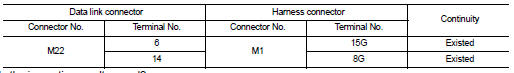
Is the inspection result normal? YES >> GO TO 3.
NO >> Repair the main line between the data link connector and the harness connector M1.
3.CHECK HARNESS CONTINUITY (OPEN CIRCUIT)
1. Disconnect the connector of ABS actuator and electric unit (control unit).
2. Check the continuity between the harness connector and the ABS actuator and electric unit (control unit) harness connector.
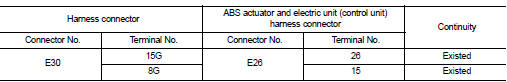
Is the inspection result normal? YES (Present error)>>Check CAN system type decision again.
YES (Past error)>>Error was detected in the main line between the data link connector and the ABS actuator and electric unit (control unit).
NO >> Repair the main line between the harness connector E30 and the ABS actuator and electric unit (control unit).
 Lan system can system (type 3)
COMPONENT DIAGNOSIS ...
 ECM branch line circuit
Diagnosis Procedure
INSPECTION PROCEDURE
1.CHECK CONNECTOR
1. Turn the ignition switch OFF.
2. Disconnect the battery cable from the negative terminal.
3. Check the following terminals and co ...
Other materials:
Can communication circuit
Diagnosis Procedure
INSPECTION PROCEDURE
1.CONNECTOR INSPECTION
1. Turn the ignition switch OFF.
2. Disconnect the battery cable from the negative terminal.
3. Disconnect all the unit connectors on CAN communication system.
4. Check terminals and connectors for damage, bend and loose con ...
B210b starter control relay
Description
Starter control relay, integrated in IPDM E/R, permits the starter relay
operation when in N or P position and
the steering is locked or unlocked. It is installed in parallel with the starter
relay.
DTC Logic
DTC DETECTION LOGIC
NOTE:
• If DTC B210B is displayed with DTC U1 ...
P0453 evap control system pressure
sensor
Description
The EVAP control system pressure sensor detects pressure in the
purge line. The sensor output voltage to the ECM increases as pressure
increases.
DTC Logic
DTC DETECTION LOGIC
DTC CONFIRMATION PROCEDURE
1.PRECONDITIONING
If DTC Confirmation Procedure has been previously cond ...
