Nissan Altima 2007-2012 Service Manual: Washer level switch signal circuit
Description
Transmits the washer level switch signal to the combination meter.
Component Function Check
1.COMBINATION METER INPUT SIGNAL
1. Select “METER/M&A” on CONSULT-III.
2. Monitor “WASHER W/L” of “DATA MONITOR” under the following conditions.
>> Inspection End.
Diagnosis Procedure
1.CHECK WASHER LEVEL SWITCH SIGNAL CIRCUIT
1. Turn ignition switch OFF.
2. Disconnect combination meter connector and washer level switch connector.
3. Check continuity between combination meter harness connector M24 (A) terminal 29 and washer level switch harness connector E208 (B) terminal 1.

4. Check continuity between combination meter harness connector M24 (A) terminal 29 and ground.

Is the inspection result normal? YES >> GO TO 2
NO >> Repair harness or connector.
2.CHECK WASHER LEVEL SWITCH GROUND CIRCUIT
Check continuity between washer fluid level switch harness connector E208 terminal 2 and ground.

Is the inspection result normal? YES >> Inspection End.
NO >> Repair harness or connector.
Component Inspection
1.CHECK WASHER FLUID LEVEL SWITCH
Check continuity between washer level switch terminals 1 and 2.
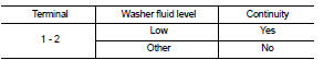
Is the inspection result normal? YES >> Inspection End.
NO >> Replace washer level switch.
 Parking brake switch signal circuit
Description
Transmits the parking brake switch signal to the combination meter.
Component Function Check
1.COMBINATION METER INPUT SIGNAL
1. Select “METER/M&A” on CONSULT-III.
2. Moni ...
 Ambient sensor signal circuit
Description
Transmits the ambient sensor signal to the combination meter.
Component Function Check
1.COMBINATION METER INPUT SIGNAL
1. Select “METER/M&A” on CONSULT-III.
2. Using “O ...
Other materials:
Rear-facing child restraint installation using LATCH
Refer to all Warnings and Cautions in the “Child
Safety” and “Child Restraint” sections before installing
a child restraint.
Follow these steps to install a rear-facing child
restraint using the LATCH system:
1. Position the child restraint on the seat. Always
follow the child restra ...
B261A push-button ignition switch
Description
IPDM E/R transmits the push-button ignition switch status via CAN
communication to BCM. BCM receives
push-button ignition switch status by hardwire input. BCM compares the 2 signals
for mismatch.
DTC Logic
DTC DETECTION LOGIC
NOTE:
• If DTC B261A is displayed with DTC U1000, ...
Normal operating condition
Description
FUEL CUT CONTROL (AT NO LOAD AND HIGH ENGINE SPEED)
If the engine speed is above 1,800 rpm under no load (for example, the
selector lever position is neutral and
engine speed is over 1,800 rpm) fuel will be cut off after some time. The exact
time when the fuel is cut off varies
b ...
