Nissan Altima (L32) 2007-2012 Service Manual: BCM (Body control module)
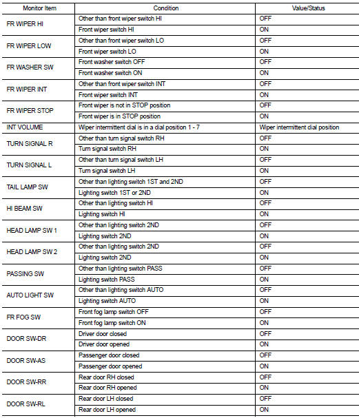
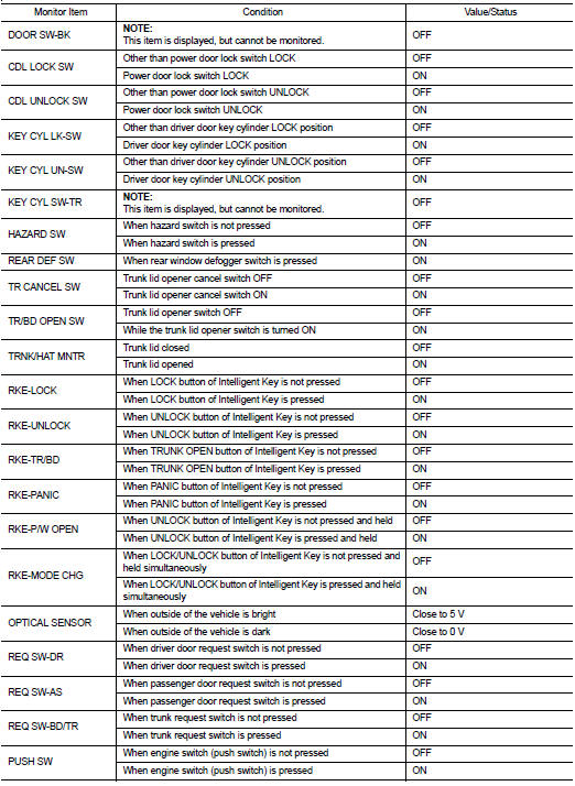
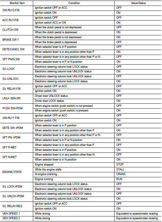
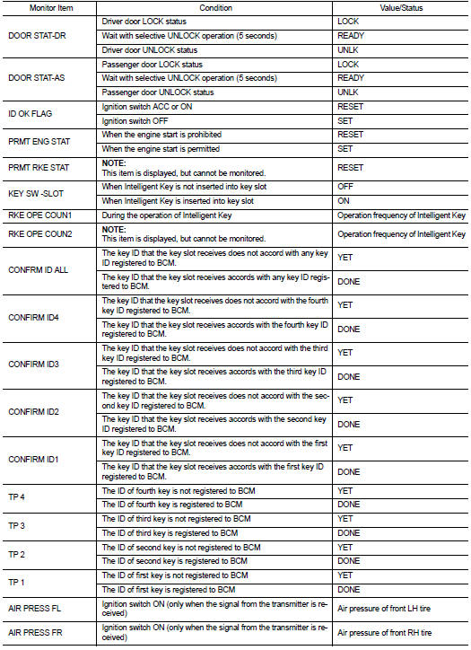
Reference Value
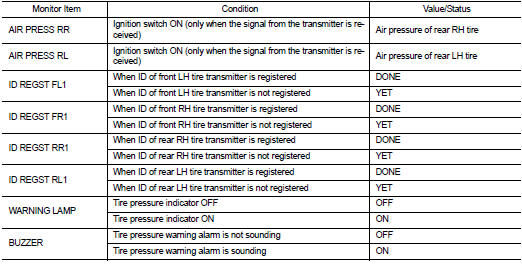
VALUES ON THE DIAGNOSIS TOOL
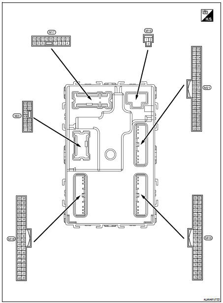
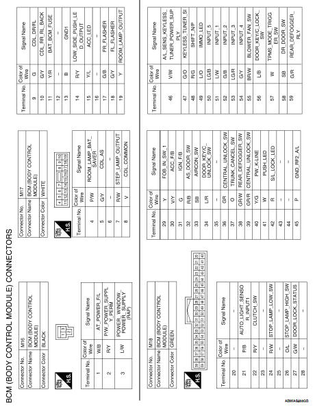
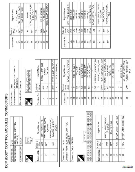
Terminal Layout
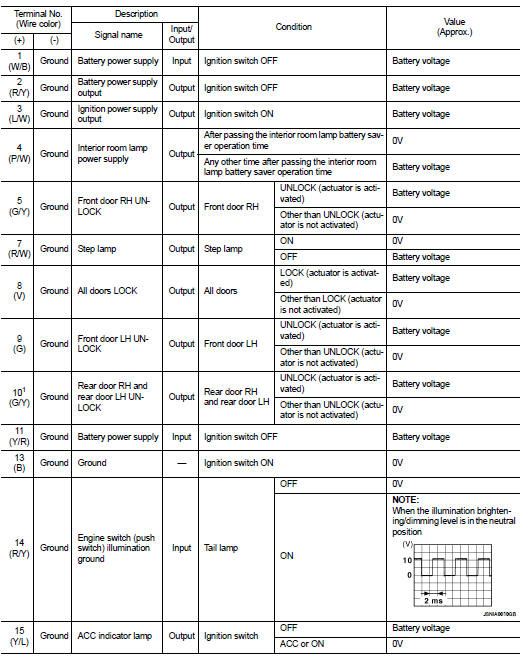
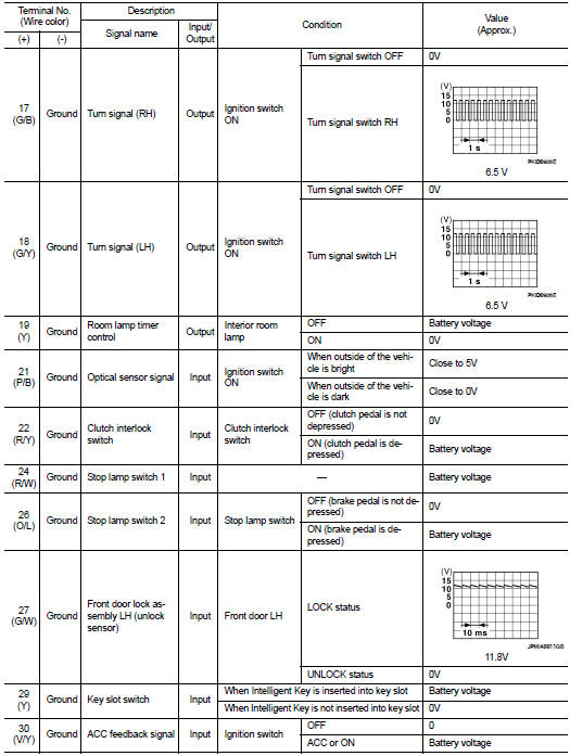
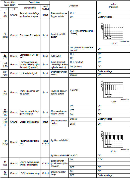
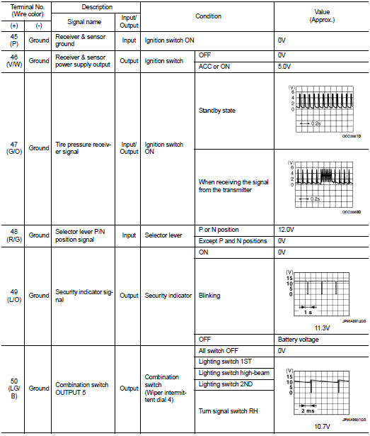
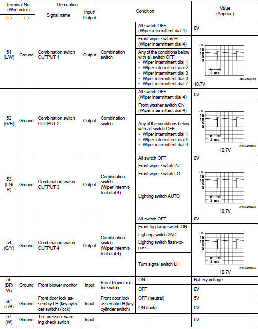
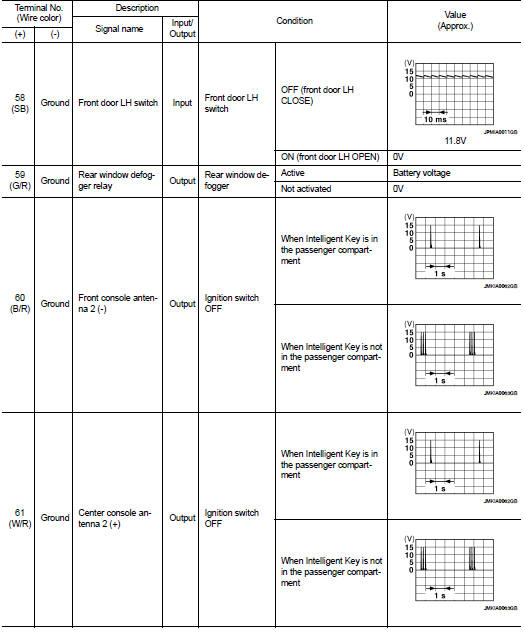
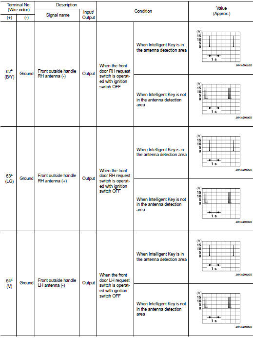
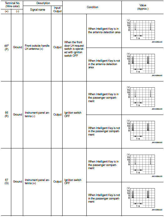
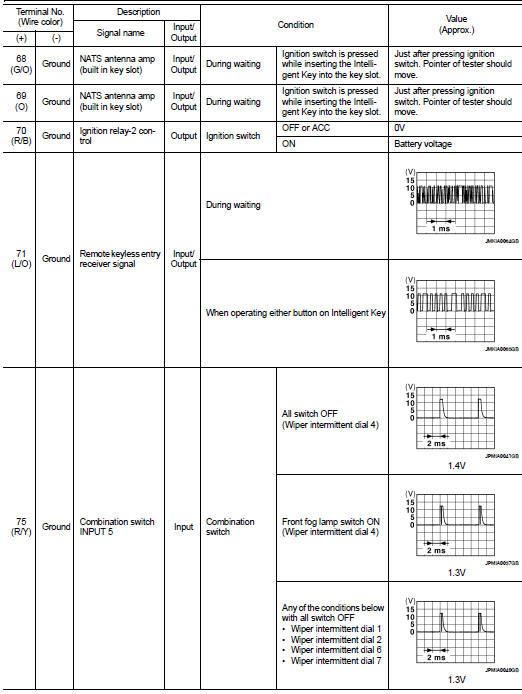
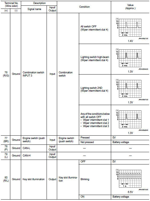
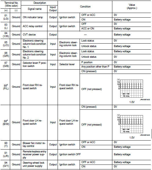
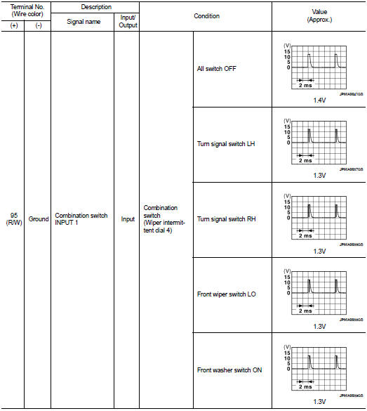
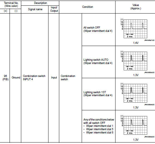
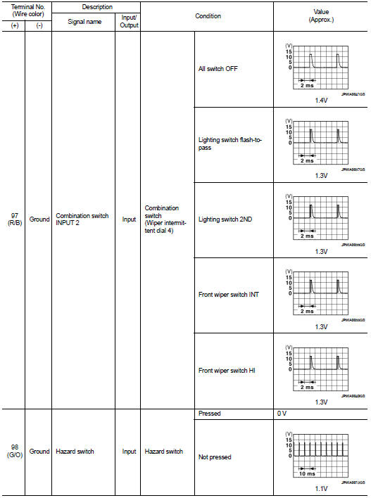
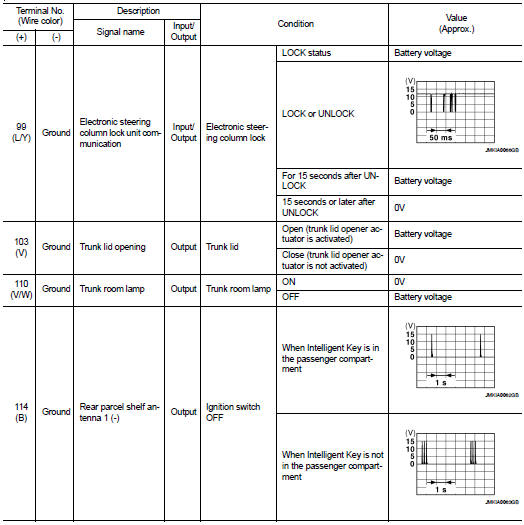
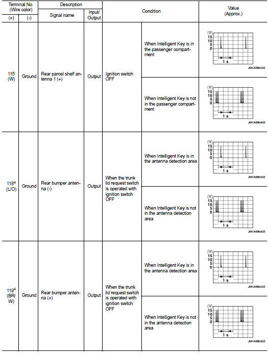
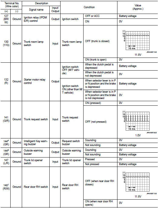
Physical Values
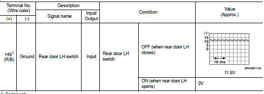
1: Sedan only
2: With LH front window anti-pinch
3: With LH and RH front window anti-pinch
4: With Intelligent Key
5: Without Intelligent Key
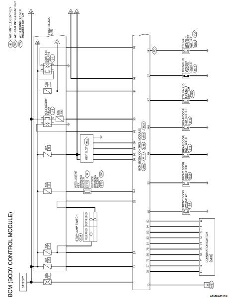
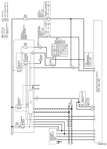
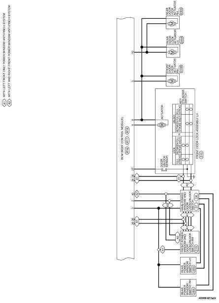
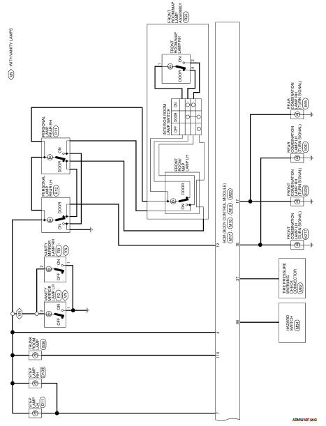
Wiring Diagram-Coupe
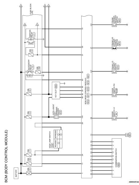
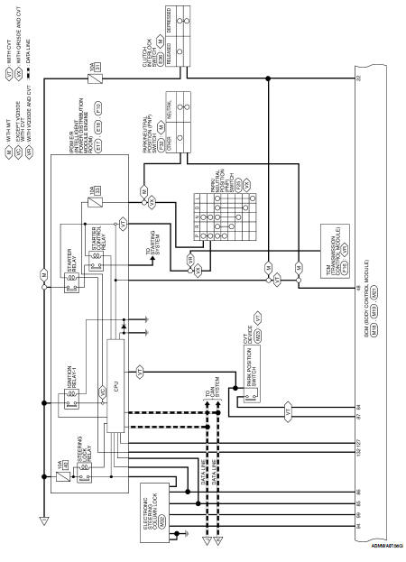
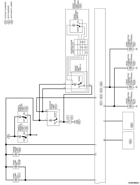
Wiring Diagram-Sedan
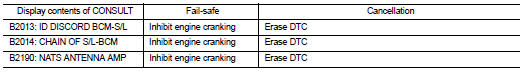
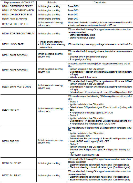
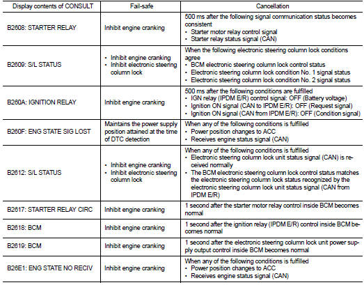
Fail Safe
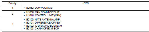
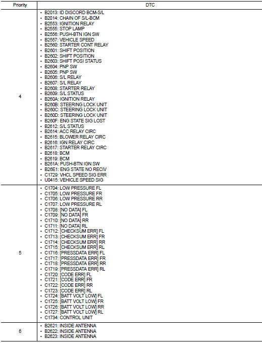
DTC Inspection Priority Chart
If some DTCs are displayed at the same time, perform inspections one by one based on the following priority chart.
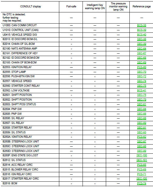
DTC Index
NOTE:
Details of time display
• CRNT: Displays when there is a malfunction now or after returning to the normal condition until turning ignition switch OFF → ON again.
• 1 - 39: Displayed if any previous malfunction is present when current condition is normal. It increases like 1 → 2 → 3...38 → 39 after returning to the normal condition whenever ignition switch OFF → ON. The counter remains at 39 even if the number of cycles exceeds it. It is counted from 1 again when turning ignition switch OFF → ON after returning to the normal condition if the malfunction is detected again.

 ECU diagnosis
...
 IPDM E/R (Intelligent power distribution
module engine room)
IPDM E/R (Intelligent power distribution
module engine room)
Reference Value
VALUES ON THE DIAGNOSIS TOOL
TERMINAL LAYOUT
PHYSICAL VALUES
Wiring Diagram — Coupe
Wiring Diagram — Sedan
Fail Safe
CAN COMMUNICA ...
Other materials:
NISSAN Intelligent Key System
WARNING
Radio waves could adversely affect
electric medical equipment. Those
who use a pacemaker should contact
the electric medical equipment
manufacturer for the possible influences
before use.
The Intelligent Key transmits radio
waves when the buttons are pressed.
The FAA advises the ra ...
U1000 can comm circuit
Description
Refer to LAN-7, "System Description".
DTC Logic
DTC DETECTION LOGIC
Diagnosis Procedure
1. PERFORM SELF DIAGNOSTIC
1. Turn ignition switch ON and wait for 2 second or more.
2. Check “SELF- DIAG RESULTS”.
Is “CAN COMM CIRCUIT” displayed?
YES >> Ref ...
AV Branch line circuit
Diagnosis Procedure
INSPECTION PROCEDURE
1.CHECK CONNECTOR
1. Turn the ignition switch OFF.
2. Disconnect the battery cable from the negative terminal.
3. Check the terminals and connectors of the AV control unit for damage, bend
and loose connection (unit
side and connector side).
I ...
