Nissan Altima (L32) 2007-2012 Service Manual: Relay control system
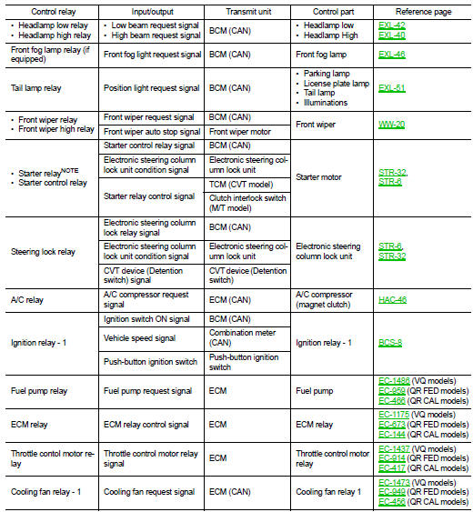
System Diagram
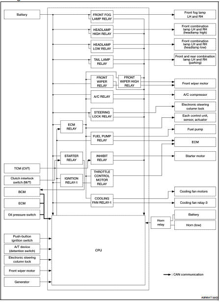
System Description
IPDM E/R activates the internal control circuit to perform the relay ON-OFF control according to the input signals from various sensors and the request signals received from control units via CAN communication.
CAUTION: IPDM E/R integrated relays cannot be removed.
NOTE: BCM controls the starter relay.
Component Parts Location
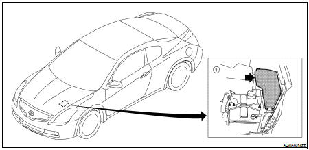
1. IPDM E/R E16, E17, E18, E200, E201, F10

 Power control system
System Diagram
System Description
COOLING FAN CONTROL
IPDM E/R controls cooling fans according to the status of the cooling fan
speed request signal received from
ECM via CAN communication. R ...
Other materials:
P0460 fuel level sensor
Description
The fuel level sensor is mounted in the fuel level sensor unit.
The sensor detects a fuel level in the fuel tank and transmits a signal to the
combination meter. The combination
meter sends the fuel level sensor signal to the ECM through CAN communication
line.
It consists o ...
Basic inspection
DIAGNOSIS AND REPAIR WORKFLOW
Work Flow
OVERALL SEQUENCE
DETAILED FLOW
1. GET INFORMATION FOR SYMPTOM
Get the detailed information from the customer about the symptom (the
condition and the environment when
the incident/malfunction occurred).
>> GO TO 2
2. CHECK DTC
1. Check DT ...
BCM (Body control module)
Reference Value
VALUES ON THE DIAGNOSIS TOOL
Terminal Layout
Physical Values
1: Sedan only
2: With LH front window anti-pinch
3: With LH and RH front window anti-pinch
4: With Intelligent Key
5: Without Intelligent Key
Wiring Diagram-Coupe
...
