Nissan Altima 2007-2012 Service Manual: Daytime running light system
System Diagram
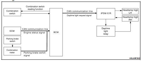
System Description
The headlamp system for Canada vehicles is equipped with a daytime light control unit that activates the high beam headlamps at approximately half illumination whenever the engine is running. If the parking brake is applied before the engine is started the daytime lights will not be illuminated. The daytime lights will illuminate once the parking brake is released. Thereafter, the daytime lights will continue to operate when the parking brake is applied.
Component Parts Location
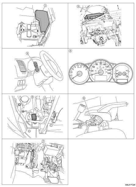
1. IPDM E/R E17, E18, E200, E201
2. BCM M16,M17, M18, M19 (view with instrument panel removed)
3. Combination switch M28
4. Combination meter M24
5. Daytime running light relay E228
6. Parking brake switch E35 (coupe with CVT) M73 (with M/T)
7. Parking brake switch E35 (sedan with CVT)
Component Description
After starting the engine with the parking brake released and the lighting switch in the OFF or 1ST position, the headlamp high beam automatically turns on. With the lighting switch in the 2nd position or with autolamps ON, the headlamps function the same as conventional light systems.
OPERATION
The BCM monitors inputs from the parking brake switch and the combination switch to determine when to activate the daytime light system. The BCM sends a daytime light request to the IPDM E/R via the CAN communication lines. The IPDM E/R grounds the daytime light relay which in turn, provides power to the ground side of the RH high beam lamp. Power flows backward throught the RH high beam lamp to the IPDM E/R, through the high beam fuses, through the LH high beam lamp circuit to the LH high beam lamp and on to ground. The high beam lamps are wired in series which causes them to illuminate at a reduced intensity.
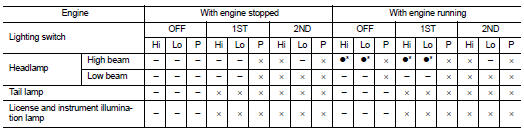
• Hi: "HIGH BEAM" position
• Lo: "LOW BEAM" position
• P: "FLASH TO PASS" position
• ×: Lamp "ON"
• –: Lamp "OFF"
•● : Lamp dims. (Added functions)
• *: When starting the engine with the parking brake released, the daytime lights will operate.
When starting the engine with the parking brake applied, the daytime lights will not operate.
 Headlamp (halogen type)
System Diagram
System Description
Control of the headlamp system operation is dependent upon the position of
the lighting switch (combination
switch). When the lighting switch is placed in the ...
 Auto light system
System Diagram
System Description
• BCM (Body Control Module) controls auto light operation according to
signals from optical sensor, lighting
switch and ignition switch.
• IPDM E/R (I ...
Other materials:
Line pressure test
Inspection and Judgment
INSPECTION
Line Pressure Test Port (A)
Line Pressure Test Procedure
1. Inspect the amount of engine oil and replenish if necessary.
2. Drive the car for about 10 minutes to warm it up so that the CVT fluid
reaches in the range of 50 to 80°C
(122 to 176°F), then ...
B2615 blower relay circuit
Description
BCM controls the various electrical components and simultaneously supplies
power according to the power
supply position.
BCM checks the power supply position internally.
DTC Logic
DTC DETECTION LOGIC
DTC CONFIRMATION PROCEDURE
1. PERFORM DTC CONFIRMATION PROCEDURE
1. Turn ...
Anti-pinch system does not operate
normally (passenger side)
Diagnosis Procedure
1. PERFORM INITIALIZATION PROCEDURE
Perform initialization procedure.
Refer to PWC-190, "ADDITIONAL SERVICE WHEN REPLACING CONTROL UNIT : Special
Repair Requirement".
Is the inspection result normal?
YES >> GO TO 2
NO >> Repair or replace the ma ...
