Nissan Altima (L32) 2007-2012 Service Manual: Can communication circuit
Diagnosis Procedure
INSPECTION PROCEDURE
1.CONNECTOR INSPECTION
1. Turn the ignition switch OFF.
2. Disconnect the battery cable from the negative terminal.
3. Disconnect all the unit connectors on CAN communication system.
4. Check terminals and connectors for damage, bend and loose connection.
Is the inspection result normal? YES >> GO TO 2.
NO >> Repair the terminal and connector.
2.CHECK HARNESS CONTINUITY (SHORT CIRCUIT)
Check the continuity between the data link connector terminals.

Is the inspection result normal? YES >> GO TO 3.
NO >> Check the harness and repair the root cause.
3.CHECK HARNESS CONTINUITY (SHORT CIRCUIT)
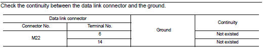
Check the continuity between the data link connector and the ground.
Is the inspection result normal? YES >> GO TO 4.
NO >> Check the harness and repair the root cause.
4.CHECK ECM AND IPDM E/R TERMINATION CIRCUIT
1. Remove the ECM and the IPDM E/R.
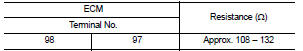
2. Check the resistance between the ECM terminals.
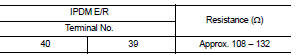
3. Check the resistance between the IPDM E/R terminals.
Is the measurement value within the specification? YES >> GO TO 5.
NO >> Replace the ECM and/or the IPDM E/R.
5.CHECK SYMPTOM
Connect all the connectors. Check if the symptoms described in the “Symptom (Results from interview with customer)” are reproduced.
Inspection result Reproduced>>GO TO 6.
Non-reproduced>>Start the diagnosis again. Follow the trouble diagnosis procedure when past error is detected.
6.CHECK UNIT REPRODUCTION
Perform the reproduction test as per the following procedure for each unit.
1. Turn the ignition switch OFF.
2. Disconnect the battery cable from the negative terminal.
3. Disconnect one of the unit connectors of CAN communication system.
NOTE: ECM and IPDM E/R have a termination circuit. Check other units first.
4. Connect the battery cable to the negative terminal. Check if the symptoms described in the “Symptom (Results from interview with customer)” are reproduced.
NOTE: Although unit-related error symptoms occur, do not confuse them with other symptoms.
Inspection result Reproduced>>Connect the connector. Check other units as per the above procedure.
Non-reproduced>>Replace the unit whose connector was disconnected.
 IPDM-E branch line circuit
Diagnosis Procedure
INSPECTION PROCEDURE
1.CHECK CONNECTOR
1. Turn the ignition switch OFF.
2. Disconnect the battery cable from the negative terminal.
3. Check the terminals and connectors ...
 Lan system can system (type 2)
COMPONENT DIAGNOSIS ...
Other materials:
Bluetooth connecting procedure
NOTE:
The connecting procedure must be performed
when the vehicle is stationary. If
the vehicle starts moving during the procedure,
the procedure will be canceled.
To connect a phone to the Bluetooth
Hands-Free Phone System:
Bluetooth Connecting Procedure
1. Touch the "Settings" key on the Launch
B ...
Moving Object Detection (MOD) (if so equipped)
The Moving Object Detection (MOD) system can
inform the driver of moving objects behind the
vehicle when backing out of garages, maneuvering
in parking lots and in other such instances.
The MOD system detects moving objects by
using image processing technology on the image
shown in the displ ...
Power supply and ground circuit
Diagnosis Procedure
1.INSPECTION START
Start engine.
Is engine running?
YES >> GO TO 8.
NO >> GO TO 2.
2.CHECK ECM POWER SUPPLY CIRCUIT-I
1. Turn ignition switch OFF and then ON.
2. Check the voltage between ECM harness connector and
ground.
Is the inspection result n ...