Nissan Altima (L32) 2007-2012 Service Manual: Microphone signal circuit (coupe)
Description
Voice signals are transmitted from the microphone to the Bluetooth control unit using the microphone signal circuits.
Diagnosis Procedure
1.CHECK HARNESS BETWEEN BLUETOOTH CONTROL UNIT AND MICROPHONE
1. Turn ignition switch OFF.
2. Disconnect Bluetooth control unit connector and microphone connector.
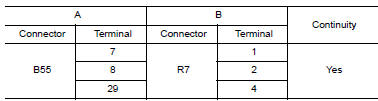
3. Check continuity between Bluetooth control unit harness connector B55 (A) and microphone harness connector R7 (B).
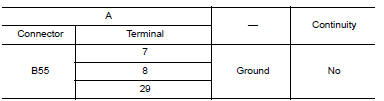
4. Check continuity between Bluetooth control unit harness connector B55 (A) and ground.
Are the continuity test results as specified? YES >> GO TO 2
NO >> Repair harness or connector.
2.CHECK MICROPHONE POWER SUPPLY
1. Connect Bluetooth control unit connector and microphone connector.
2. Turn ignition switch ON.
3. Check voltage between microphone harness connector R7 terminal 4 and ground.

Is voltage reading approx. 5 volts? YES >> GO TO 3
NO >> Replace Bluetooth control unit. Refer to AV-235, "Removal and Installation - Coupe".
3.CHECK MICROPHONE SIGNAL
Check signal between Bluetooth control unit harness connector B55 terminals 7 and 8.

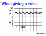
Are voltage readings as specified? YES >> Replace Bluetooth control unit. Refer to AV-235, "Removal and Installation - Coupe".
NO >> Replace microphone. Refer to AV-233, "Removal and Installation".
 Sound signal circuit (sedan)
SATELLITE RADIO TUNER
Description
Left and right channel audio signals are supplied from the satellite radio
tuner to the audio unit through the
sound signal circuits.
Diagnosis Procedur ...
 Microphone signal circuit (sedan)
Description
Voice signals are transmitted from the microphone to the Bluetooth control
unit using the microphone signal
circuits.
Diagnosis Procedure
1.CHECK HARNESS BETWEEN BLUETOOTH CONTROL UN ...
Other materials:
P0139 HO2S2
Description
The heated oxygen sensor 2, after three way catalyst (manifold),
monitors the oxygen level in the exhaust gas on each bank.
Even if switching characteristics of the air fuel ratio (A/F) sensor 1
are shifted, the air-fuel ratio is controlled to stoichiometric, by the signal
from th ...
B1065 – B1068, B1070 – B1073 passenger
airbag module
Description
DTC B1065 – B1068, B1070 – B1073 PASSENGER AIR BAG MODULE
The passenger air bag module is dual stage and wired to the air bag diagnosis
sensor unit. The air bag diagnosis
sensor unit will monitor for opens and shorts in detected lines to the passenger
air bag module.
PART LOC ...
Evaporative emission system
System Diagram
EVAPORATIVE EMISSION LINE DRAWING
1. Intake manifold collector
2. EVAP service port
3. EVAP canister purge volume control
solenoid valve
A. From next figure
1. EVAP control system pressure sensor
2. EVAP canister vent control valve
3. EVAP canister
A. To previous figu ...
