Nissan Altima (L32) 2007-2012 Service Manual: Encoder
DRIVER SIDE
Description
Detects condition of the front power window motor LH operation and transmits to main power window and door lock/unlock switch as pulse signal.
Component Function Check
1. CHECK ENCODER OPERATION
Does front door glass LH perform AUTO open/close operation normally with main power window and door lock/unlock switch? Is the inspection result normal? YES >> Encoder operation is OK.
NO >> Refer to PWC-121, "DRIVER SIDE : Diagnosis Procedure".
Diagnosis Procedure
Encoder Circuit Check
1. CHECK ENCODER OPERATION
1. Connect front power window motor LH.
2. Turn ignition switch ON.
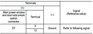
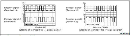
3. Check signal between main power window and door lock/unlock switch connector and ground with oscilloscope.
Is the inspection result normal? YES >> Check intermittent incident. Refer to GI-42, "Intermittent Incident".
NO >> GO TO 2
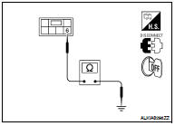
2. CHECK FRONT POWER WINDOW MOTOR LH POWER SUPPLY
1. Turn ignition switch ON.
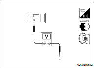
2. Check voltage between front power window motor LH connector and ground.
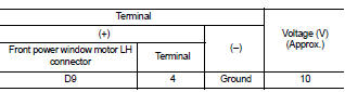
Is the measurement value within the specification? YES >> GO TO 4
NO >> GO TO 3
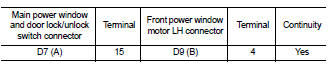
3. CHECK HARNESS CONTINUITY 1
1. Turn ignition switch OFF.
2. Disconnect main power window and door lock/unlock switch and front power window motor LH.
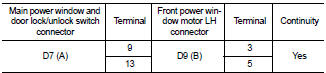
3. Check continuity between main power window and door lock/ unlock switch connector (A) and front power window motor connector (B).
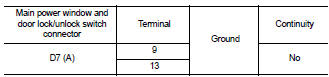
4. Check continuity between main power window and door lock/unlock switch connector (A) and ground.
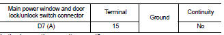
Is the inspection result normal? YES >> Replace main power window and door lock/unlock switch. Refer to PWC-186, "Removal and Installation". After that, refer to PWC-123, "DRIVER SIDE : Special Repair Requirement".
NO >> Repair or replace harness.
4. CHECK GROUND CIRCUIT
1. Turn ignition switch OFF.
2. Disconnect front power window motor LH.
3. Check continuity between front power window motor LH connector and ground.
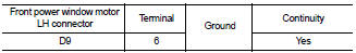
Is the inspection result normal? YES >> GO TO 6
NO >> GO TO 5
5. CHECK HARNESS CONTINUITY 2
1. Disconnect main power window and door lock/unlock switch.
2. Check continuity between main power window and door lock/ unlock switch connector (A) and front power window motor LH connector (B).
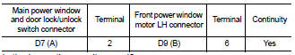
Is the inspection result normal? YES >> Replace main power window and door lock/unlock switch. Refer to PWC-186, "Removal and Installation". After that, refer to PWC-123, "DRIVER SIDE : Special Repair Requirement".
NO >> Repair or replace harness.
6. CHECK HARNESS CONTINUITY 3
1. Disconnect main power window and door lock/unlock switch.
2. Check continuity between main power window and door lock/ unlock switch connector (A) and front power window motor LH connector (B).
3. Check continuity between main power window and door lock/ unlock switch connector (A) and ground.
Is the inspection result normal? YES >> Replace front power window motor LH. Refer to GW-19, "Removal and Installation". After that, refer to PWC-123, "DRIVER SIDE : Special Repair Requirement".
NO >> Repair or replace harness.
Special Repair Requirement
1. PERFORM INITIALIZATION PROCED
Perform initialization procedure.
Refer to PWC-95, "ADDITIONAL SERVICE WHEN REPLACING CONTROL UNIT : Special Repair Requirement".
Is the inspection result normal? YES >> Inspection end.
NO >> Check intermittent incident. Refer to GI-42, "Intermittent Incident".
 Rear RH
Description
Door glass moves UP/DOWN by receiving the signal from main power window and
door lock/unlock switch or
rear power window switch RH.
Component Function Check
1. CHECK POWER WIND ...
 Door switch
Description
Detects door open/close condition and transmits the signal to BCM.
Component Function Check
1. CHECK FRONT DOOR SWITCH INPUT SIGNAL
Check (“DOOR SW-DR” and “DOOR SW-AS”) in †...
Other materials:
Turn signal and hazard warning
lamp system
Wiring Diagram - Coupe
Wiring Diagram - Sedan
...
B2606 steering lock relay
Description
The steering lock relay ON signal is transmitted to IPDM E/R by BCM via CAN
communication.
IPDM E/R turns the steering lock relay ON and transmits the release of the
steering to BCM.
DTC Logic
DTC DETECTION LOGIC
NOTE:
• If DTC B2606 is displayed with DTC U1000, first per ...
B2190, P1610 nats antenna amp
Description
Performs ID verification through BCM and keyfob when push-button ignition
switch is pressed.
Prohibits the release of steering lock or start of engine when an unregistered
ID of keyfob is used.
DTC Logic
DTC DETECTION LOGIC
DTC CONFIRMATION PROCEDURE
1.PERFORM DTC CONFIRMA ...
