Nissan Altima (L32) 2007-2012 Service Manual: B2616 ignition relay circuit
Description
BCM controls the various electrical components and simultaneously supplies power according to the power supply position.
BCM checks the power supply position internally.
DTC Logic
DTC DETECTION LOGIC
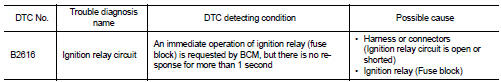
DTC CONFIRMATION PROCEDURE
1. PERFORM DTC CONFIRMATION PROCEDURE
1. Turn ignition switch ON under the following conditions, and wait for at least 1 second.
- CVT selector lever is in the P or N position
- Release brake pedal
2. Check “Self diagnostic result” with CONSULT-III.
Is DTC detected? YES >> Go to PCS-71, "Diagnosis Procedure".
NO >> Inspection End.
Diagnosis Procedure
1. CHECK IGNITION RELAY POWER SUPPLY
1. Turn ignition switch OFF.
2. Disconnect ignition relay.
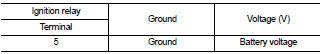
3. Check voltage between ignition relay harness connector and ground under the following conditions.

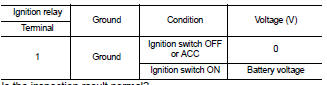
Is the inspection result normal? YES >> GO TO 3
NO >> GO TO 2
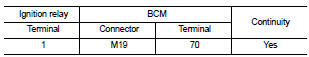
2. CHECK IGNITION RELAY POWER SUPPLY CIRCUIT
1. Turn ignition switch OFF.
2. Disconnect BCM harness connector.
3. Check continuity between ignition relay harness connector (A) and BCM harness connector (B).
4. Check continuity between ignition relay harness connector (A) and ground.
Is the inspection result normal? YES >> GO TO 6
NO >> Repair or replace harness.
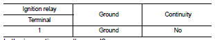
3. CHECK IGNITION RELAY GROUND CIRCUIT
1. Turn ignition switch OFF.
2. Check continuity between ignition relay harness connector and ground.
Is the inspection result normal? YES >> GO TO 4
NO >> Repair or replace harness.
4. CHECK IGNITION RELAY POWER SUPPLY CIRCUIT-2
Check voltage between ignition relay harness connector and ground.
Is the inspection result normal? YES >> GO TO 5
Is the inspection result normal? YES >> GO TO 5
NO >> Repair or replace harness.
5. CHECK IGNITION RELAY
Refer to PCS-73, "Component Inspection (Ignition Relay)".
Is the inspection result normal? YES >> GO TO 6
NO >> Replace ignition relay.
6. CHECK INTERMITTENT INCIDENT
Refer to GI-42, "Intermittent Incident".
>> Inspection End.
Component Inspection (Ignition Relay)
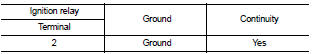
1. CHECK IGNITION RELAY
1. Turn ignition switch OFF.
2. Remove ignition relay.
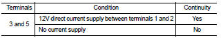
3. Check the continuity between ignition relay terminals under the following conditions.
Is the inspection result normal? YES >> Inspection End.
NO >> Replace ignition relay.
 B2615 blower relay circuit
Description
BCM controls the various electrical components and simultaneously supplies
power according to the power
supply position.
BCM checks the power supply position internally.
DTC Logic ...
 B2618 BCM
Description
BCM controls the various electrical components and simultaneously supplies
power according to the power
supply position.
BCM checks the power supply position internally.
DTC Logic
...
Other materials:
Engine start function
System Diagram
System Description
INPUT/OUTPUT SIGNAL CHART
SYSTEM DESCRIPTION
• The engine start function of remote keyless entry system is a system that
makes it possible to start and stop
the engine without removing the key. It verifies the electronic ID using two-way
communicati ...
Removal and installation
TRANSAXLE ASSEMBLY
Exploded View
1. Air breather hose
2. CVT fluid level gauge
3. CVT fluid charging pipe
4. O-ring
5. Copper washer
6. Fluid cooler tube
7. Fluid cooler tube
8. CVT assembly
A. Refer to TM-447, "Removal and Installation".
Removal and Installation
REMOVAL
1. ...
On board diagnostic (OBD) System
Diagnosis Description
DESCRIPTION
The CVT system has two self-diagnostic systems.
The first is the emission-related on board diagnostic system (OBD-II) performed
by the TCM in combination
with the ECM. The malfunction is indicated by the MIL (malfunction indicator
lamp) and is stored as a ...
