Nissan Altima (L32) 2007-2012 Service Manual: Communication signal circuit (sedan) satellite radio tuner
Description
Communication signals are exchanged between the audio unit and satellite radio tuner using the communication circuits.
Diagnosis Procedure
1.CHECK HARNESS - 1
1. Turn ignition switch OFF.
2. Disconnect satellite radio tuner (factory installed) connector B123 and audio unit connector M45.
3. Check continuity between satellite radio tuner (factory installed) harness connector B123 (A) terminal 28 and audio unit harness connector M45 (B) terminal 38.
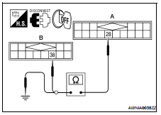

4. Check continuity between satellite radio tuner (factory installed) harness connector B123 (A) terminal 28 and ground.

Are continuity results as specified? YES >> GO TO 2
NO >> Repair harness or connector.
2.CHECK HARNESS - 2
1. Check continuity between satellite radio tuner (factory installed) harness connector B123 (A) terminal 29 and audio unit harness connector M45 (B) terminal 39.
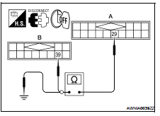

2. Check continuity between satellite radio tuner (factory installed) harness connector B123 (A) terminal 29 and ground.

Are continuity results as specified? YES >> GO TO 3
NO >> Repair harness or connector.
3.CHECK HARNESS - 3
1. Check continuity between satellite radio tuner (factory installed) harness connector B123 (A) terminal 30 and audio unit harness connector M45 (B) terminal 40.

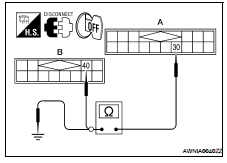
2. Check continuity between satellite radio tuner (factory installed) harness connector B123 (A) terminal 30 and ground.

Are continuity results as specified? YES >> GO TO 4
NO >> Repair harness or connector.
4.CHECK REQ1 SIGNAL
1. Connect satellite radio tuner (factory installed) connector and audio unit connector.
2. Turn ignition switch to ACC 3. Check signal between satellite radio tuner (factory installed) harness connector B123 terminal 28 and ground with CONSULT-III or oscilloscope.
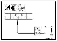

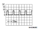
Are voltage readings as specified? YES >> GO TO 5
NO >> Replace audio unit. Refer to AV-215, "Removal and Installation".
5.CHECK TXD SIGNAL
Check signal between satellite radio tuner (factory installed) harness connector B123 terminal 29 and ground with CONSULT-III or oscilloscope.
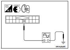

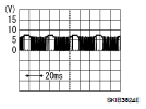
Are the voltage readings as specified? YES >> GO TO 6
NO >> Replace satellite radio tuner. Refer to AV-223, "Removal and Installation - Sedan".
6.CHECK RXD SIGNAL
Check signal between satellite radio tuner (factory installed) harness connector B123 terminal 30 and ground with CONSULT-III or oscilloscope.

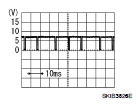
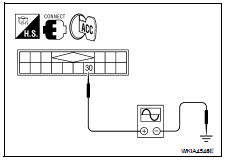
Are the voltage readings as specified? YES >> Replace satellite radio tuner. Refer to AV-223, "Removal and Installation - Sedan".
NO >> Replace audio unit. Refer to AV-215, "Removal and Installation".
 Satellite radio tuner
Description
Communication signals are exchanged between the audio unit and satellite
radio tuner using the communication
circuits.
Diagnosis Procedure
1.CHECK HARNESS - 1
. Turn ignition switc ...
 Sound signal circuit (coupe)
SATELLITE RADIO TUNER
Description
Left and right channel audio signals are supplied from the satellite radio
tuner to the audio unit through the
sound signal circuits.
Diagnosis Procedure
LEF ...
Other materials:
P1553 Battery current sensor
Description
The power generation voltage variable control enables fuel consumption to
be decreased by reducing the
engine load which is caused by the power generation of the generator. The
battery current sensor is installed
to the battery cable at the negative terminal. The sensor measures t ...
B2609 steering status
Description
There are 2 switches in the electronic steering column lock (steering
lock/unlock switch 1 and 2). BCM compares
those two switches conditions to judge the present steering status.
DTC Logic
DTC DETECTION LOGIC
NOTE:
• If DTC B2609 is displayed with DTC U1000, first perform the ...
STRG branch line circuit
Diagnosis Procedure
INSPECTION PROCEDURE
1.CHECK CONNECTOR
1. Turn the ignition switch OFF.
2. Disconnect the battery cable from the negative terminal.
3. Check the terminals and connectors of the steering angle sensor for damage,
bend and loose connection
(unit side and connector side) ...
