Nissan Altima (L32) 2007-2012 Service Manual: Ground
Ground Distribution
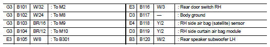
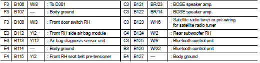
MAIN HARNESS
ENGINE ROOM HARNESS
FRONT END MODULE HARNESS
ENGINE CONTROL HARNESS
BODY HARNESS
BODY NO. 2 HARNESS
HARNESS
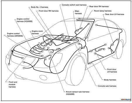
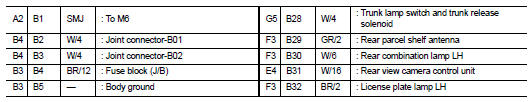
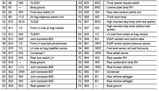
Harness Layout
HOW TO READ HARNESS LAYOUT
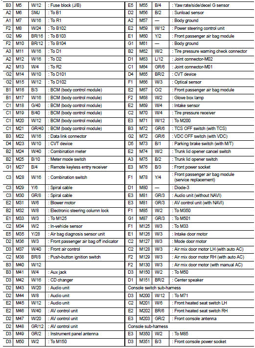
The following Harness Layouts use a map style grid to help locate connectors on the drawings: • Main Harness, Console Sub-harness and Console Switch Subharness
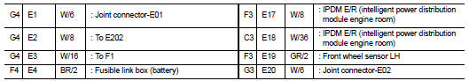
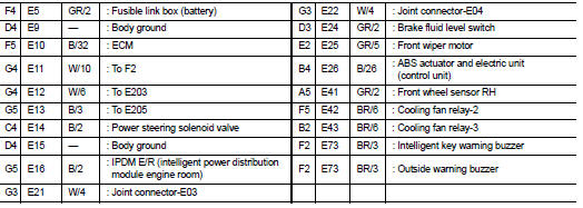
• Engine Room Harness
• Engine Room Harness (Passenger Compartment)
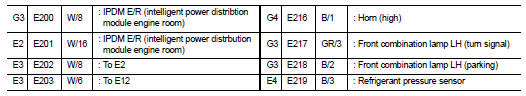
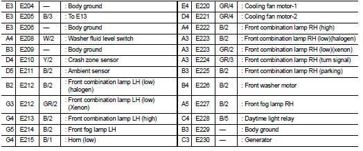
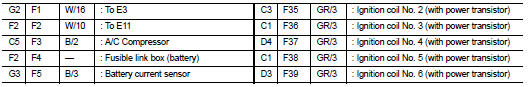
• Front End Module Harness
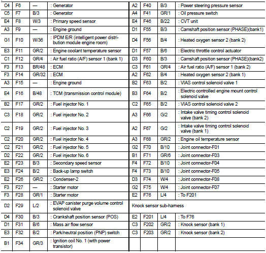
• Engine Control Harness (VQ35DE) and Knock Sensor Sub-harness
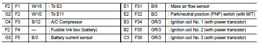
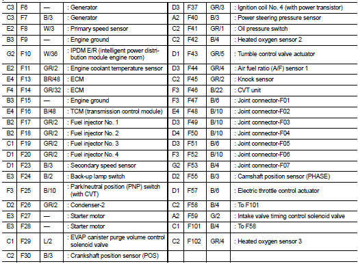
• Engine Control Harness (QR25DE)
• Body Harness
• Body No. 2 Harness
• Room Lamp Harness
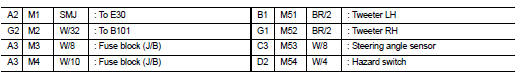
To use the grid reference
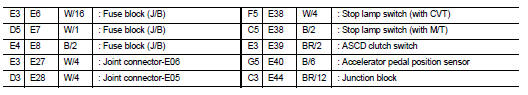
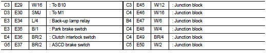
1. Find the desired connector number on the connector list.
2. Find the grid reference.
3. On the drawing, find the crossing of the grid reference letter column and number row.
4. Find the connector number in the crossing zone.
5. Follow the line (if used) to the connector.
OUTLINE
MAIN HARNESS
ENGINE ROOM HARNESS
ENGINE ROOM HARNESS (PASSENGER COMPARTMENT)
FRONT END MODULE HARNESS
ENGINE CONTROL HARNESS (VQ35DE)
ENGINE CONTROL HARNESS (QR25DE)
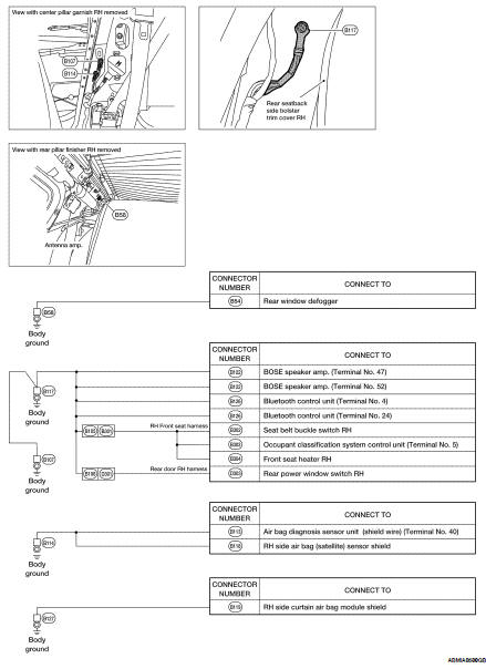
BODY HARNESS
BODY NO. 2 HARNESS
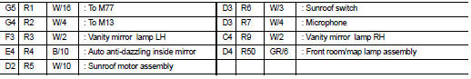
ROOM LAMP HARNESS
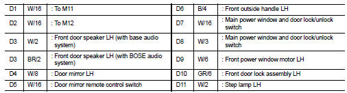
FRONT DOOR LH HARNESS
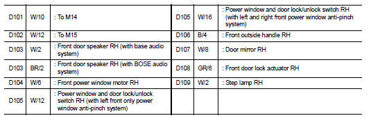
FRONT DOOR RH HARNESS
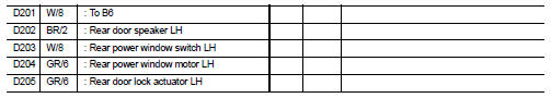
REAR DOOR LH HARNESS
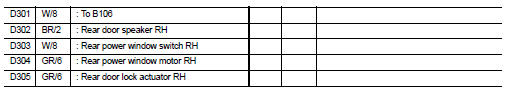
REAR DOOR RH HARNESS
 Power supply routing circuit
Wiring Diagram — Battery Power Supply —
Wiring Diagram — Accessory Power Supply —
Wiring Diagram — Ignition Power Supply —
Fuse
• If fuse is ...
 Electrical units location
Electrical Units Location
ENGINE COMPARTMENT
PASSENGER COMPARTMENT
LUGGAGE COMPARTMENT
HARNESS CONNECTOR
Description
HARNESS CONNECTOR (TAB-LOCKING TYPE)
• The tab-locking type conne ...
Other materials:
AV branch line circuit
Diagnosis Procedure
INSPECTION PROCEDURE
1.CHECK CONNECTOR
1. Turn the ignition switch OFF.
2. Disconnect the battery cable from the negative terminal.
3. Check the terminals and connectors of the AV control unit for damage, bend
and loose connection (unit
side and connector side).
I ...
B260b steering lock unit
Description
The steering lock unit performs the check by itself according to the steering
status.
DTC Logic
DTC DETECTION LOGIC
DTC CONFIRMATION PROCEDURE
1.PERFORM DTC CONFIRMATION PROCEDURE
1. Press the push-button ignition switch, when steering is locked.
2. Check “Self diagnostic ...
Cooling system
Cooling Circuit
1. Thermostat
2. Water control valve
3. Water control valve housing (Water outlet)
4. Cylinder block (Thermostat housing)
5. Water inlet
6. Radiator
7. Water pump
8. Cylinder block
9. Cylinder head
A. Open
B. Closed
C. To electric throttle control
D. To oil cooler
E. ...
