Nissan Altima (L32) 2007-2012 Service Manual: ABS branch line circuit
Diagnosis Procedure
INSPECTION PROCEDURE
1.CHECK CONNECTOR
1. Turn the ignition switch OFF.
2. Disconnect the battery cable from the negative terminal.
3. Check the terminals and connectors of the ABS actuator and electric unit (control unit) for damage, bend and loose connection (unit side and connector side).
Is the inspection result normal? YES >> GO TO 2.
NO >> Repair the terminal and connector.
2.CHECK HARNESS FOR OPEN CIRCUIT
1. Disconnect the connector of ABS actuator and electric unit (control unit).
2. Check the resistance between the ABS actuator and electric unit (control unit) harness connector terminals.
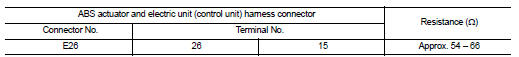
Is the measurement value within the specification? YES >> GO TO 3.
NO >> Repair the ABS actuator and electric unit (control unit) branch line.
3.CHECK POWER SUPPLY AND GROUND CIRCUIT
Check the power supply and the ground circuit of the ABS actuator and electric unit (control unit). Refer to the following.
• Models with ABS: BRC-41, "Wiring Diagram - Coupe" or BRC-46, "Wiring Diagram - Sedan" • Models with TCS: BRC-109, "Wiring Diagram - Coupe" or BRC-115, "Wiring Diagram - Sedan" • Models with VDC: BRC-207, "Wiring Diagram - Coupe" or BRC-215, "Wiring Diagram - Sedan" Is the inspection result normal? YES (Present error)>>Replace the ABS actuator and electric unit (control unit). Refer to the following.
• Models with ABS: BRC-66, "Exploded View" • Models with TCS: BRC-137, "Exploded View" • Models with VDC: BRC-239, "Exploded View" YES (Past error)>>Error was detected in the ABS actuator and electric unit (control unit) branch line.
NO >> Repair the power supply and the ground circuit.
 M&A branch line circuit
Diagnosis Procedure
INSPECTION PROCEDURE
1.CHECK CONNECTOR
1. Turn the ignition switch OFF.
2. Disconnect the battery cable from the negative terminal.
3. Check the terminals and connectors ...
 IPDM-E branch line circuit
Diagnosis Procedure
INSPECTION PROCEDURE
1.CHECK CONNECTOR
1. Turn the ignition switch OFF.
2. Disconnect the battery cable from the negative terminal.
3. Check the following terminals and co ...
Other materials:
P1572 ASCD Brake switch
Description
When the brake pedal is depressed, ASCD brake switch is turned OFF and stop
lamp switch is turned ON.
ECM detects the state of the brake pedal by those two types of input (ON/OFF
signal).
Refer to EC-1090, "System Diagram" for the ASCD function.
DTC Logic
DTC DETEC ...
P0340 CMP sensor (phase)
Description
The camshaft position sensor (PHASE) senses the retraction of
camshaft (INT) to identify a particular cylinder. The camshaft position
sensor (PHASE) senses the piston position.
When the crankshaft position sensor (POS) system becomes inoperative,
the camshaft position sensor (PHAS ...
Extending engine run time
The remote start feature can be extended one
time by performing the steps listed in “Remote
starting the vehicle” in this section. Run time will
be calculated as follows:
● The first 10 minute run time will start when
the remote start function is performed.
● The second 10 minu ...
