Nissan Altima (L32) 2007-2012 Service Manual: B2614 ACC relay circuit
Description
BCM controls the various electrical components and simultaneously supplies power according to the power supply position.
BCM checks the power supply position internally.
DTC Logic
DTC DETECTION LOGIC
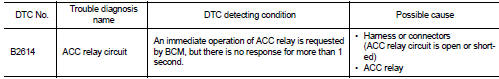
DTC CONFIRMATION PROCEDURE
1. PERFORM DTC CONFIRMATION PROCEDURE
1. Turn the power supply position to ACC under the following conditions, and wait for at least 1 second.
- CVT selector lever is in the P or N position.
- Release the brake pedal.
2. Check “Self diagnostic result” with CONSULT-III.
Is DTC detected? YES >> Go to PCS-65, "Diagnosis Procedure".
NO >> Inspection End.
Diagnosis Procedure
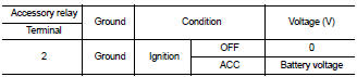
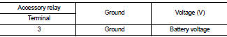
1. CHECK ACCESSORY RELAY POWER SUPPLY
1. Turn ignition switch OFF.
2. Disconnect accessory relay.
3. Check voltage between accessory relay harness connector and ground under the following conditions.
Is the inspection result normal? YES >> GO TO 3
NO >> GO TO 2
2. CHECK ACCESSORY RELAY POWER SUPPLY CIRCUIT
1. Turn ignition switch OFF.
2. Disconnect BCM harness connector.
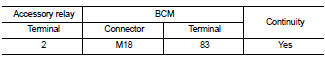
3. Check continuity between accessory relay harness connector (A) and BCM harness connector (B).
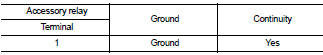
4. Check continuity between accessory relay harness connector and ground.

Is the inspection result normal? YES >> GO TO 6
NO >> Repair or replace harness.
3. CHECK ACCESSORY RELAY GROUND CIRCUIT
1. Turn ignition switch OFF.
2. Check continuity between accessory relay harness connector and ground.
Is the inspection result normal? YES >> GO TO 4
NO >> Repair or replace harness.
4. CHECK ACCESSORY RELAY POWER SUPPLY CIRCUIT-2
Check voltage between accessory relay harness connector and ground.
Is the inspection result normal? YES >> GO TO 5
NO >> Repair or replace harness.
5. CHECK ACCESSORY RELAY
Refer to PCS-67, "Component Inspection (Accessory Relay)".
YES or NO
YES >> GO TO 6
NO >> Replace accessory relay.
6. CHECK INTERMITTENT INCIDENT
Refer to GI-42, "Intermittent Incident".
>> Inspection End.
Component Inspection (Accessory Relay)
1. CHECK ACCESSORY RELAY
1. Turn ignition switch OFF.
2. Remove accessory relay.
3. Check the continuity between accessory relay terminals under the following conditions.
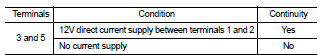
Is the inspection result normal? YES >> Inspection End.
NO >> Replace accessory relay
 B2611 ACC relay
Description
BCM turns ON the ACC relay to supply ACC power to each ECU when the power
supply position changes to
ACC.
BCM check ACC relay ON request for consistency with the actual ACC relay
...
 B2615 blower relay circuit
Description
BCM controls the various electrical components and simultaneously supplies
power according to the power
supply position.
BCM checks the power supply position internally.
DTC Logic ...
Other materials:
CVT Position
Inspection and Adjustment
INSPECTION
1. Place selector lever in “P” position, and turn ignition switch ON (engine
stop).
2. Make sure that selector lever can be shifted to other than “P” position when
brake pedal is depressed.
Also make sure that selector lever can be shifted fro ...
Water control valve
Removal and Installation
1. Thermostat
2. O-ring
3. Engine coolant inlet
4. Water control valve
5. Gasket
6. Engine coolant outlet
7. Copper washer
8. Engine coolant temperature sensor
9. Heater pipe
A. To electric throttle control
B. To oil cooler
C. To heater
D. To heater
E. To ele ...
Oil pan and oil strainer
Removal and Installation
1. Oil level gauge guide
2. Oil pan, upper
3. Cylinder block
4. Oil filter
5. Oil strainer
6. Drain plug
7. Oil pan, lower
8. Rear plate cover
9. O-ring
A. To oil pan, lower
REMOVAL
WARNING:
To avoid the danger of being scalded, never drain the engine oil when ...
