Nissan Altima (L32) 2007-2012 Service Manual: Steering switch
Description
When one of the steering wheel audio control switches is pushed, the resistance in steering switch circuit changes depending on which button is pushed.
Diagnosis Procedure
1.CHECK STEERING SWITCH RESISTANCE
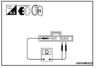
1. Disconnect steering switch connector M88.
2. Check resistance between steering switch connector terminals.
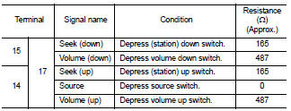
Do the steering switches check OK? YES >> GO TO 2
NO >> Replace steering switch. Refer to AV-225, "Removal and Installation".
2.CHECK HARNESS
1. Turn ignition switch OFF.
2. Disconnect audio unit connector M43 and spiral cable connector M30.
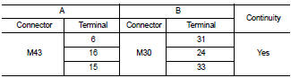
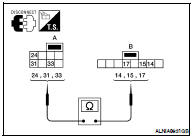
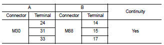
3. Check continuity between audio unit harness connector M43 (A) and spiral cable harness connector M30 (B).
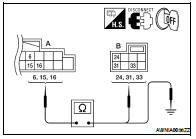
4. Check continuity between audio unit connector M43 (A) and ground.
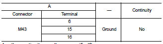
Are the continuity results as specified? YES >> GO TO 3
NO >> Repair harness.
3.SPIRAL CABLE CHECK
1. Disconnect spiral cable connector M88.
2. Check continuity between spiral cable harness connector M30 (A) and M88 (B).
Does the spiral cable check OK? YES >> Inspection End.
NO >> Replace spiral cable. Refer to SR-8, "Removal and Installation".
 Rear speaker
Description
The audio unit sends audio signals to the rear speakers using the rear
speaker circuits.
Diagnosis Procedure
1.HARNESS CHECK
1. Disconnect audio unit connector M43 (A) and suspect s ...
 Communication signal circuit
(coupe)
Communication signal circuit
(coupe)
SATELLITE RADIO TUNER
Description
Communication signals are exchanged between the audio unit and satellite
radio tuner using the communication
circuits.
Diagnosis Procedure
1.CHECK HARN ...
Other materials:
ECM branch line circuit
Diagnosis Procedure
INSPECTION PROCEDURE
1.CHECK CONNECTOR
1. Turn the ignition switch OFF.
2. Disconnect the battery cable from the negative terminal.
3. Check the following terminals and connectors for damage, bend and loose
connection (unit side and connector
side).
- ECM
- Harnes ...
Variable induction air system
System Diagram
System Description
INPUT/OUTPUT SIGNAL CHART
*: ECM determines the start signal status by the signals of engine speed and
battery voltage.
SYSTEM DESCRIPTION
In the medium speed range, the ECM sends the ON signal to the VIAS control
solenoid valve. This signal
introdu ...
Encoder
DRIVER SIDE
Description
Detects condition of the power window motor LH operation and transmits to
main power window and door
lock/unlock switch as pulse signal.
Component Function Check
1. CHECK ENCODER OPERATION
Does door glass LH perform AUTO open/close operation normally with main power ...
