Nissan Altima (L32) 2007-2012 Service Manual: Push-button ignition switch position indicator
Description
The switch that changes the power supply position.
BCM maintains the power supply position status.
BCM changes the power supply position with the operation of the push-button ignition switch.
Component Function Check
1. CHECK FUNCTION

1. Check push-button ignition switch (“LOCK INDICATOR”,“ACC INDICATOR” and “IGNITION ON IND”) in Active Test Mode with CONSULT-III.

Is the inspection result normal? YES >> Inspection End..
NO >> Refer to PCS-80, "Diagnosis Procedure".
Diagnosis Procedure
1. CHECK PUSH-BUTTON IGNITION SWITCH INPUT SIGNAL
1. Turn ignition switch OFF.
2. Disconnect push-button ignition switch.
3. Check voltage between push-button ignition switch harness connector and ground.
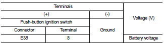
Is the inspection result normal? YES >> GO TO 2
NO >> Check the following.
• 10A fuse [No. 9, located in fuse block (J/B)] • Harness for open or short between push-button ignition switch and fuse.
2. CHECK PUSH-BUTTON IGNITION SWITCH CIRCUIT
1. Disconnect BCM and push-button ignition switch.
2. Check continuity between BCM harness connector and pushbutton ignition switch harness connector.
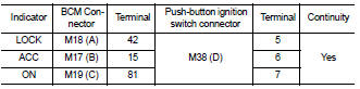
3. Check continuity between BCM harness connector and ground.
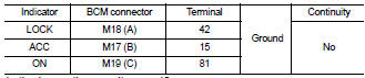
Is the inspection result normal? YES >> GO TO 3
NO >> Repair or replace harness.
3. CHECK PUSH-BUTTON IGNITION SWITCH
Refer to PCS-82, "Component Inspection".
Is the inspection result normal? YES >> GO TO 4
NO >> Replace push-button ignition switch. Refer to SEC-208, "Removal and Installation".
4. CHECK INTERMITTENT INCIDENT
Refer to GI-42, "Intermittent Incident".
>> Inspection End.
Component Inspection
1. CHECK PUSH-BUTTON IGNITION SWITCH
Check push-button ignition switch.
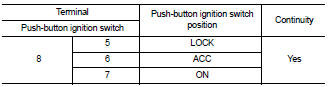
Is the inspection result normal? YES >> Inspection End.
NO >> Replace push-button ignition switch. Refer to SEC-208, "Removal and Installation".
 IPDM E/R (Intelligent power distribution
module engine room)
IPDM E/R (Intelligent power distribution
module engine room) ECU diagnosis