Nissan Altima (L32) 2007-2012 Service Manual: B1023 passenger air bag off indicator
Description
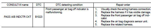
DTC B1023 FRONT PASSENGER AIR BAG OFF INDICATOR
The front passenger air bag off indicator is wired to the air bag diagnosis sensor unit. The air bag diagnosis sensor unit monitors the front passenger air bag off indicator and circuit for failures.
PART LOCATION
Refer to SRC-7, "SRS Component Parts Location".
DTC Logic
DTC DETECTION LOGIC
With CONSULT-lll
Without CONSULT-lll
DTC CONFIRMATION PROCEDURE (With CONSULT-lll)
1.INSPECTION START
Turn ignition switch ON.
>> GO TO 2.
2.CHECK SELF-DIAG RESULT
Check for the DTC on CONSULT-lll.
Is the DTC detected? YES >> Refer to SRC-52, "Diagnosis Procedure (Component Diagnosis)".
NO >> Inspection End.
DTC CONFIRMATION PROCEDURE (Without CONSULT-lll)
NOTE: SRS will not enter diagnosis mode if no malfunction is detected in user mode.
1.IGNITION SWITCH
Turn ignition switch ON.
>> GO TO 2
2.IGNITION SWITCH
After air bag warning lamp lights for 7 seconds, turn ignition switch OFF within 1 second.
>> GO TO 3
3.WAIT TIME
Wait more than 3 seconds.
>> GO TO 4
4.REPEAT STEPS
Repeat steps 1 to 3 twice.
>> GO TO 5
5.IGNITION SWITCH
Turn ignition switch ON.
>> GO TO 6
6.DIAGNOSTIC MODE
SRS system is now in diagnostic mode and AIR BAG warning lamp flashes. Refer to SRC-70, "Trouble Diagnosis without CONSULT-III".
>> END
Diagnosis Procedure (Component Diagnosis)
Recheck SRS after each replacement.
1.HARNESS CONNECTOR
Is there any visible damage to the connector? YES or NO
Is there any visible damage to the connector? YES or NO
2.WIRING HARNESS
Is there any visible damage to the harness? YES or NO
Is there any visible damage to the harness? YES or NO
Is there any visible damage to the harness? YES or NO
Replace the front passenger air bag off indicator. Refer to IP-12, "Removal and Installation".
>> GO TO 4
4.AIR BAG DIAGNOSIS SENSOR UNIT
Replace the air bag diagnosis sensor unit. Refer to SR-17, "Removal and Installation".
>> GO TO 5
5.RELATED HARNESS
Replace the related harness.
>> END
 B1xxx air bag diagnosis sensor unit
 B1017 – b1022 occupant classification
system
B1017 – b1022 occupant classification
system