Nissan Altima (L32) 2007-2012 Service Manual: B210F PNP/Clutch interlock switch
Description
IPDM E/R confirms the shift position with the following signals.
• Park/neutral position (PNP) switch
• Shift position signal from BCM (CAN)
DTC Logic
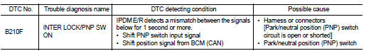
DTC DETECTION LOGIC
NOTE: • If DTC B210F is displayed with DTC U1000, first perform the trouble diagnosis for DTC U1000. Refer to SEC-433, "DTC Logic" • If DTC B210F is displayed with DTC U1010, first perform the trouble diagnosis for DTC U1010. Refer to SEC-433, "DTC Logic".
DTC CONFIRMATION PROCEDURE
1.PERFORM DTC CONFIRMATION PROCEDURE
1. Turn ignition switch ON under the following conditions and wait for at least 1 second.
- CVT selector lever is in the P or N position
- Do not depress the brake pedal
2. Check “Self diagnostic result” with CONSULT-III.
Is DTC detected? YES >> Refer to SEC-450, "Diagnosis Procedure".
NO >> Inspection End.
Diagnosis Procedure
1.CHECK DTC WITH BCM
Refer to BCS-91, "DTC Index".
Is the inspection result normal? YES >> GO TO 2
NO >> Repair or replace malfunctioning parts.
2.CHECK PNP SWITCH INPUT SIGNAL
1. Turn ignition switch OFF.
2. Disconnect IPDM E/R harness connector.
3. Turn ignition switch ON.
4. Check voltage between IPDM E/R harness connector and ground under following condition.
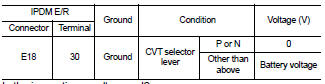
Is the inspection result normal? YES >> Replace IPDM E/R. Refer to PCS-48, "Removal and Installation".
NO >> GO TO 3
3.CHECK PNP SWITCH CIRCUIT FOR CONTINUITY
1. Turn ignition switch OFF.
2. Check continuity between IPDM E/R harness connector terminals 72 and 74.
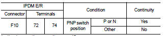
Is the inspection result normal? YES >> GO TO 4
NO >> GO TO 5
4.CHECK PNP SWITCH CIRCUIT FOR SHORT
Check continuity between IPDM E/R harness connector terminals 72, 74 and ground.
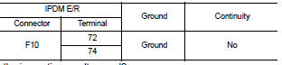
Is the inspection result normal? YES >> Replace the IPDM E/R. Refer to PCS-48, "Removal and Installation".
NO >> Repair or replace harness.
5.CHECK PNP SWITCH INPUT SIGNAL CIRCUIT
1. Disconnect PNP switch harness connector.
2. Check continuity between PNP switch and IPDM E/R harness connectors.
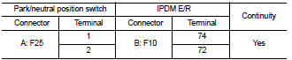
3. Check continuity between PNP switch harness connector and ground.
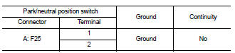
Is the inspection result normal? YES >> Replace PNP switch.
NO >> Repair harness or connector.
 B210E starter relay
 B2110 PNP/Clutch interlock switch