Nissan Altima (L32) 2007-2012 Service Manual: B2601 shift position
Description
BCM confirms the shift position with the following 2 signals.
• CVT selector lever
• P position signal from IPDM E/R (CAN)
DTC Logic
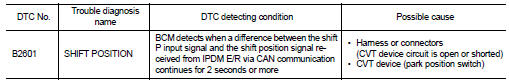
DTC DETECTION LOGIC
NOTE: • If DTC B2601 is displayed with DTC U1000, first perform the trouble diagnosis for DTC U1000. Refer to SEC-36, "DTC Logic".
• If DTC B2601 is displayed with DTC U1010, first perform the trouble diagnosis for DTC U1010. Refer to SEC-37, "DTC Logic".
• If DTC B2601 is displayed with DTC B2605, first perform the trouble diagnosis for DTC B2605. Refer to SEC-86, "DTC Logic".
DTC CONFIRMATION PROCEDURE
1.PERFORM DTC CONFIRMATION PROCEDURE
1. Turn ignition switch ON under the following conditions, and wait for at least 2 seconds.
- CVT selector lever is in the P position.
- Do not depress the brake pedal.
2. Check “Self diagnostic result” with CONSULT-III.
3. Turn ignition switch ON under the following conditions, and wait for at least 2 seconds.
- CVT selector lever is in other than P position.
- Do not depress the brake pedal.
4. Check “Self diagnostic result” with CONSULT-III.
Is DTC detected? YES >> Refer to SEC-76, "Diagnosis Procedure".
NO >> Inspection End.
Diagnosis Procedure
1.CHECK CVT DEVICE POWER SUPPLY
1. Turn ignition switch to ACC.
2. Disconnect CVT device (park position switch) harness connector.
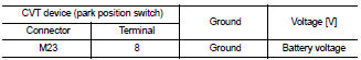
3. Check voltage between CVT device (park position switch) harness connector and ground.
Is the inspection result normal? YES >> GO TO 3
NO >> GO TO 2
2.CHECK CVT DEVICE POWER SUPPLY CIRCUIT
1. Disconnect BCM harness connector.
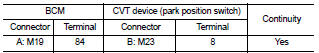
2. Check continuity between BCM harness connector M19 (A) terminal 84 and CVT device (park position switch) harness connector M23 (B) terminal 8.
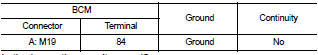
3. Check continuity between BCM harness connector M19 (A) terminal 84 and ground.
Is the inspection result normal? YES >> Replace BCM. Refer to BCS-96, "Removal and Installation".
NO >> Repair harness or connector.
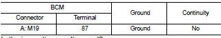
3.CHECK CVT DEVICE CIRCUIT (BCM)
1. Disconnect BCM harness connector and IPDM E/R harness connector.
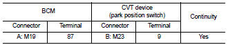
2. Check continuity between BCM harness connector M19 (A) terminal 87 and CVT device (park position switch) harness connector M23 (B) terminal 9.
3. Check continuity between BCM harness connector M19 (A) terminal 87 and ground.
Is the inspection result normal? YES >> GO TO 4
NO >> Repair harness or connector.
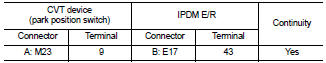
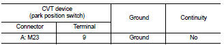
4.CHECK CVT DEVICE CIRCUIT (IPDM E/R)
1. Disconnect BCM harness connector.
2. Check continuity between CVT device (park position switch) harness connector M23 (A) terminal 9 and IPDM E/R harness connector E17 (B) terminal 43.
3. Check continuity between CVT device (park position switch) harness connector M23 (A) terminal 9 and ground.
Is the inspection result normal? YES >> GO TO 5
NO >> Repair harness or connector.
5.CHECK CVT DEVICE
Refer to SEC-78, "Component Inspection".
Is the inspection result normal? YES >> GO TO 6
NO >> Replace CVT device. Refer to TM-255, "Removal and Installation" (RE0F09B) or TM-431, "Removal and Installation" (RE0F10A).
6.CHECK INTERMITTENT INCIDENT
Refer to GI-42, "Intermittent Incident".
>> Inspection End.
Component Inspection
1.CHECK CVT DEVICE (PARK POSITION SWITCH)
1. Turn ignition switch OFF.
2. Disconnect CVT device (park position switch) harness connector.
3. Check continuity between CVT device (park position switch) terminals as follows.
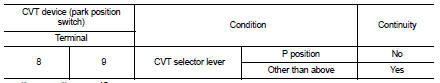
Is the inspection result normal? YES >> Inspection End.
NO >> Replace CVT device. Refer to TM-255, "Removal and Installation" (RE0F09B) or TM-431, "Removal and Installation" (RE0F10A).
 B2560 starter control relay
 B2602 shift position