Nissan Altima (L32) 2007-2012 Service Manual: B2608 starter relay
Description
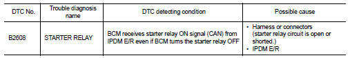
Located in IPDM E/R, it runs the starter motor. The starter relay is turned ON by the BCM when the ignition switch is in START position. IPDM E/R transmits the starter relay ON signal to BCM via CAN communication.
DTC Logic
DTC DETECTION LOGIC
NOTE: • If DTC B2608 is displayed with DTC U1000, first perform the trouble diagnosis for DTC U1000. Refer to SEC-36, "DTC Logic".
• If DTC B2608 is displayed with DTC U1010, first perform the trouble diagnosis for DTC U1010. Refer to SEC-37, "DTC Logic".
DTC CONFIRMATION PROCEDURE
1.PERFORM DTC CONFIRMATION PROCEDURE
1. Press the push-button ignition switch under the following conditions.
- CVT selector lever is in the P or N position.
- Depress the brake pedal.
2. Check “Self diagnostic result” with CONSULT-III.
Is DTC detected? YES >> Refer to SEC-91, "Diagnosis Procedure".
NO >> Inspection End.
Diagnosis Procedure
1.CHECK STARTER RELAY
1. Turn ignition switch ON.
2. Check voltage between BCM harness connector and ground under the following condition.
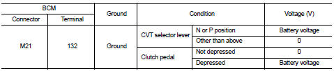
Is the measurement value within the specification? YES >> GO TO 3
NO >> GO TO 2
2.CHECK STARTER RELAY CIRCUIT
1. Turn ignition switch OFF.
2. Disconnect BCM harness connector M21 and IPDM E/R harness connector E17.
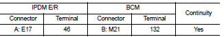
3. Check continuity between IPDM E/R harness connector and BCM harness connector.
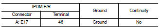
4. Check continuity between IPDM E/R harness connector and ground.
Is the inspection result normal? YES >> Replace IPDM E/R. Refer to PCS-48, "Removal and Installation".
NO >> Repair harness or connector.
3.CHECK INTERMITTENT INCIDENT
Refer to GI-42, "Intermittent Incident".
>> Inspection End.
 B2607 steering lock relay
 B2609 steering status