Nissan Altima (L32) 2007-2012 Service Manual: B2611 ACC relay
Description
BCM turns ON the ACC relay to supply ACC power to each ECU when the power supply position changes to ACC.
BCM check ACC relay ON request for consistency with the actual ACC relay operation status.
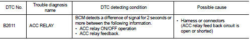
DTC Logic
DTC DETECTION LOGIC
NOTE: • If DTC B2611 is displayed with DTC U1000, first perform the trouble diagnosis for DTC U1000. Refer to PCS-58, "DTC Logic" .
• If DTC B2611 is displayed with DTC U1010, first perform the trouble diagnosis for DTC U1010. Refer to PCS-59, "DTC Logic".
DTC CONFIRMATION PROCEDURE
1. PERFORM DTC CONFIRMATION PROCEDURE
1. Turn the power supply position to ACC under the following conditions, and wait for at least 2 seconds.
- CVT selector lever is in P or N position
- Brake not depressed
2. Check “Self diagnostic result” with CONSULT-III.
Is DTC detected? YES >> Go to PCS-63, "Diagnosis Procedure".
NO >> Inspection End.
Diagnosis Procedure
1.CHECK ACC RELAY FEED BACK INPUT SIGNAL
Check voltage between BCM harness connector and ground under the following conditions.
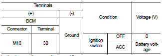
Is the inspection result normal? YES >> GO TO 5
NO >> GO TO 2
2.CHECK ACC RELAY POWER SUPPLY CIRCUIT
1. Turn ignition switch OFF.
2. Disconnect ACC relay.
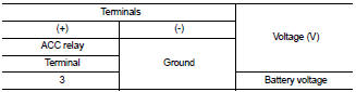
3. Check voltage between ACC relay harness connector and ground.
Is the inspection result normal? YES >> GO TO 3
NO >> Repair or replace harness.
3. CHECK FUSE
Check 10A fuse [No. 19, located in the fuse block (J/B)].
Is the inspection result normal? YES >> GO TO 4
NO >> Replace fuse.
4. CHECK ACC RELAY FEEDBACK CIRCUIT
1. Disconnect BCM harness connector.
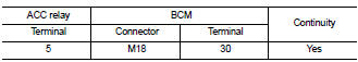
2. Check continuity between ACC relay harness connector (A) and BCM harness connector (B).
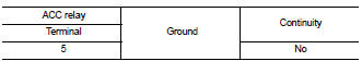
3. Check continuity between ACC relay harness connector and ground.
Is the inspection result normal? YES >> GO TO 5
NO >> Repair or replace harness.
5. CHECK INTERMITTENT
Refer to GI-42, "Intermittent Incident".
>> Inspection End.
 B260A ignition relay
 B2614 ACC relay circuit