Nissan Altima (L32) 2007-2012 Service Manual: B26e1 no reception of engine status signal
Description
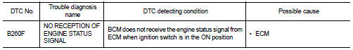
BCM receives the engine status signal from ECM via CAN communication.
DTC Logic
DTC DETECTION LOGIC
NOTE: • If DTC B26E1 is displayed with DTC U1000, first perform the trouble diagnosis for DTC U1000. Refer to SEC-36, "DTC Logic".
• If DTC B26E1 is displayed with DTC U1010, first perform the trouble diagnosis for DTC U1010. Refer to SEC-37, "DTC Logic".
DTC CONFIRMATION PROCEDURE
1.PERFORM DTC CONFIRMATION PROCEDURE
1. Turn ignition switch ON under the following conditions.
- CVT selector lever is in the P or N position.
- Do not depress the brake pedal.
2. Check “Self diagnostic result” with CONSULT-III.
Is DTC detected? YES >> Refer to SEC-110, "Diagnosis Procedure".
NO >> Inspection End.
Diagnosis Procedure
1.INSPECTION START
1. Turn ignition switch ON.
2. Check “Self diagnostic result” with CONSULT-III.
3. Touch “ERASE”.
4. Perform DTC Confirmation Procedure.
See SEC-110, "DTC Logic".
Is the DTC B26E1 displayed again? YES >> GO TO 2
NO >> Inspection End.
2.REPLACE ECM
1. Replace ECM.
2. Refer to EC-1048, "BASIC INSPECTION : Special Repair Requirement" (VQ35DE), EC-24, "BASIC INSPECTION : Special Repair Requirement" (QR25DE California), EC-560, "BASIC INSPECTION : Special Repair Requirement" (QR25DE except California).
>> Inspection End.
 B261a push-button ignition switch
 Power supply and ground circuit