Nissan Altima (L32) 2007-2012 Service Manual: Basic inspection
DIAGNOSIS AND REPAIR WORKFLOW
Work Flow
OVERALL SEQUENCE
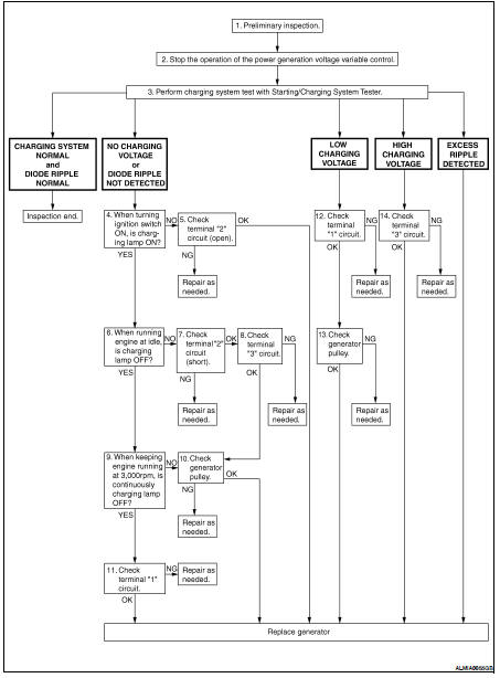
DETAILED FLOW
NOTE: To ensure a complete and thorough diagnosis, the battery, starter and generator test segments must be done as a set from start to finish.
1.PRELIMINARY INSPECTION
Perform the preliminary inspection. Refer to CHG-7, "Inspection Procedure".
>> GO TO 2
2.DISABLE THE POWER GENERATION VOLTAGE VARIABLE CONTROL SYSTEM
Disable the power generation voltage variable control with either of the following procedures.
• After selecting “ENGINE” on the “SELECT SYSTEM” screen of CONSULT-III, set the “ALTERNATOR DUTY” value to 0 % by selecting “ALTERNATOR DUTY” with “Active Test”. Continue “Active Test” until the end of inspection. (When the DUTY value is 0 or 100 %, the normal power generation is performed according to the characteristic of the IC regulator of the generator.) • Turn the ignition switch OFF, disconnect the battery current sensor connector and leave it disconnected during the course of the test.
NOTE: Running the engine with the battery current sensor disconnected will cause DTC's (P1550-P1554) to set.
After finishing the inspection, connect the battery current sensor connector and erase the self-diagnostic results history of the engine using CONSULT-III.
>> GO TO 3
3.DIAGNOSIS WITH STARTING/CHARGING SYSTEM TESTER
Perform the charging system test using Starting/Charging System Tester (J-44373). For details and operating instructions, refer to Technical Service Bulletin.
Test result
CHARGING SYSTEM NOMAL>>Charging system is normal and will also show “DIODE RIPPLE” test result.
NO CHARGING VOLTAGE>>GO TO 4
LOW CHARGING VOLTAGE>>GO TO 12
HIGH CHARGING VOLTAGE>>GO TO 14
HIGH CHARGING VOLTAGE>>GO TO 14 DIODE RIPPLE NORMAL>>Diode ripple is OK and will also show “CHARGING VOLTAGE” test result.
EXCESS RIPPLE DETECTED>>Replace the generator. Perform “DIODE RIPPLE” test again using Starting/ Charging System Tester (J-44373) to confirm repair.
DIODE RIPPLE NOT DETECTED>>GO TO 4
4.INSPECTION WITH CHARGE WARNING LAMP (IGNITION SWITCH IS ON)
Turn the ignition switch ON.
Does the charge warning lamp illuminate? YES >> GO TO 6
NO >> GO TO 5
5.TERMINAL“2” (OPEN) CIRCUIT INSPECTION
Check terminal “2” circuit for open circuits. Refer to CHG-11, "Diagnosis Procedure".
Is the terminal “2” circuit normal? YES >> Replace generator. Refer to CHG-27, "Removal and Installation".
NO >> Repair as needed.
6.INSPECTION WITH CHARGE WARNING LAMP (IDLING)
Start the engine and run it at idle.
Does the charge warning lamp turn OFF? YES >> GO TO 9
NO >> GO TO 7
7.TERMINAL “2”(SHORT) CIRCUIT INSPECTION
Check terminal “2” circuit for short to ground. Refer to CHG-11, "Diagnosis Procedure".
Is the terminal “2” circuit normal?
YES >> GO TO 8
NO >> Repair as needed.
8.TERMINAL“3” CIRCUIT INSPECTION
Check terminal “3” circuit. Refer to CHG-12, "Diagnosis Procedure".
Is the terminal “3” circuit normal? YES >> GO TO 10
NO >> Repair as needed.
9.INSPECTION WITH CHARGE WARNING LAMP (ENGINE AT 3,000 RPM)
Increase and maintain the engine speed at 3,000 rpm.
Does the charge warning lamp remain off? YES >> GO TO 11
NO >> GO TO 10
10.INSPECTION OF GENERATOR PULLEY
Check generator pulley. Refer to CHG-29, "Inspection".
Is generator pulley normal? YES >> Replace generator. Refer to CHG-27, "Removal and Installation".
NO >> Repair as needed.
11.TERMINAL “1” CIRCUIT INSPECTION
Check terminal “1””circuit. Refer to CHG-10, "Diagnosis Procedure".
Is terminal “1” circuit normal? YES >> Replace generator. Refer to CHG-27, "Removal and Installation".
NO >> Repair as needed.
12.TERMINAL “1” CIRCUIT INSPECTION
Check terminal “1” circuit. Refer to CHG-10, "Diagnosis Procedure".
Is terminal “1” circuit normal? YES >> GO TO 13
NO >> Repair as needed.
13.INSPECTION OF GENERATOR PULLEY
Check generator pulley. Refer to CHG-29, "Inspection".
Is generator pulley normal? YES >> Replace generator. Refer to CHG-27, "Removal and Installation".
NO >> Repair as needed.
14.TERMINAL “3” CIRCUIT INSPECTION
Check terminal “3” circuit. Refer to CHG-12, "Diagnosis Procedure".
Is the terminal “3” circuit normal? YES >> Replace generator. Refer to CHG-27, "Removal and Installation".
NO >> Repair as needed.
 Charging system
 Function diagnosis