Nissan Altima (L32) 2007-2012 Service Manual: Basic inspection
DIAGNOSIS AND REPAIR WORKFLOW
Work Flow
OVERALL SEQUENCE
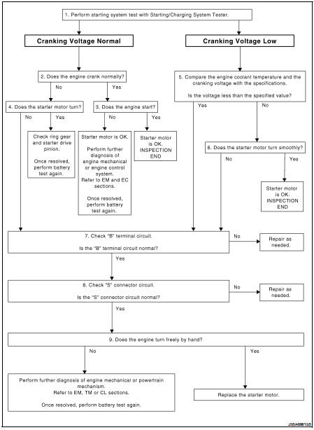
DETAILED FLOW
NOTE: To ensure a complete and thorough diagnosis, the battery, starter motor and alternator test segments must be done as a set from start to finish.
1.DIAGNOSIS WITH STARTING/CHARGING SYSTEM TESTER
Perform the starting system test with Starting/Charging System Tester (J-44373). For details and operating instructions, refer to Technical Service Bulletin.
Test result CRANKING VOLTAGE NORMAL>>GO TO 2
CRANKING VOLTAGE LOW>>GO TO 5
CHARGE BATTERY>>Perform the slow battery charging procedure. (Initial rate of charge is 10A for 12 hours.) Perform battery test again. Refer to Technical Service Bulletin.
REPLACE BATTERY>>Before replacing battery, clean the battery cable clamps and battery posts. Perform battery test again. Refer to Technical Service Bulletin. If second test result is “REPLACE BATTERY”, then do so. Perform battery test again to confirm repair.
2.CRANKING CHECK
Check that the starter motor operates properly.
Does the engine crank normally? YES >> GO TO 3
NO >> GO TO 4
3.ENGINE START CHECK
Check that the engine starts.
Does the engine start? YES >> Starter motor is OK. Inspection end.
NO >> Perform further diagnosis of engine mechanical or engine control system. Refer to EM and EC sections. Once resolved, perform battery test again.
4.STARTER MOTOR ACTIVATION
Check that the starter motor operates.
Does the starter motor turn? YES >> Check ring gear and starter motor drive pinion. Once resolved, perform battery test again.
NO >> GO TO 7
5.COMPARISON BETWEEN ENGINE COOLANT AND CRANKING VOLTAGE
Compare the engine coolant temperature and verify the cranking voltage is within specification.
Minimum Specification of Cranking Voltage Referencing Coolant Temperature
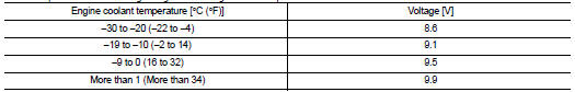
Is the voltage less than the specified value? YES >> GO TO 7
NO >> GO TO 6
6.STARTER OPERATION
Check the starter operation.
Does the starter motor turn smoothly? YES >> Starter motor is OK. Inspection end.
NO >> GO TO 7
7.“B” TERMINAL CIRCUIT INSPECTION
Check “B” terminal circuit. Refer to STR-8, "Diagnosis Procedure".
Is “B” terminal circuit normal?
YES >> GO TO 8 NO >> Repair as needed.
8.“S” CONNECTOR CIRCUIT INSPECTION
Check “S” connector circuit. Refer to STR-9, "Diagnosis Procedure".
Is “S” connector circuit normal? YES >> GO TO 9
NO >> Repair as needed.
9.ENGINE ROTATION STATUS
Check that the engine can be rotated by hand.
Does the engine turn freely by hand? YES >> Replace starter motor.
NO >> Perform further diagnosis of engine mechanical or powertrain mechanism. Refer to EM, TM or CL sections. Once resolved, perform battery test again. Refer to Technical Service Bulletin.
 Starting system QR25DE
 Function diagnosis