Nissan Altima (L32) 2007-2012 Service Manual: BCM (Body control module)
Reference Value
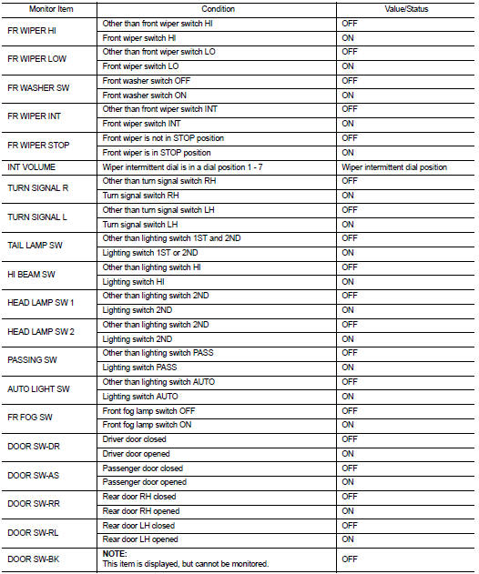
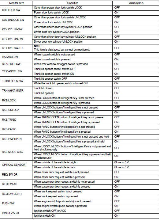
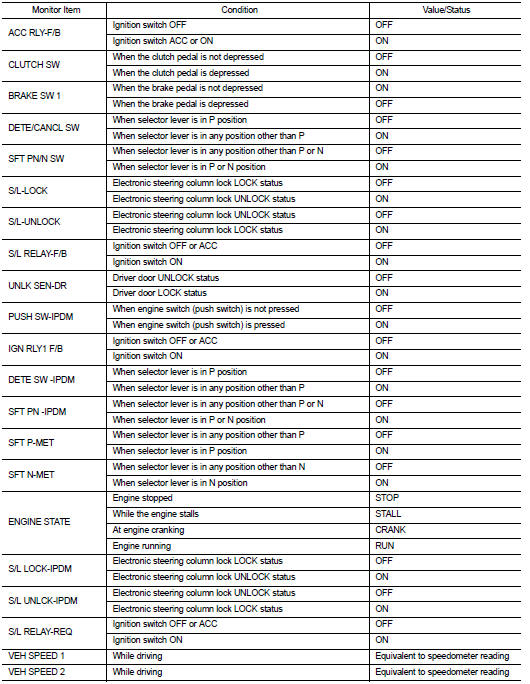
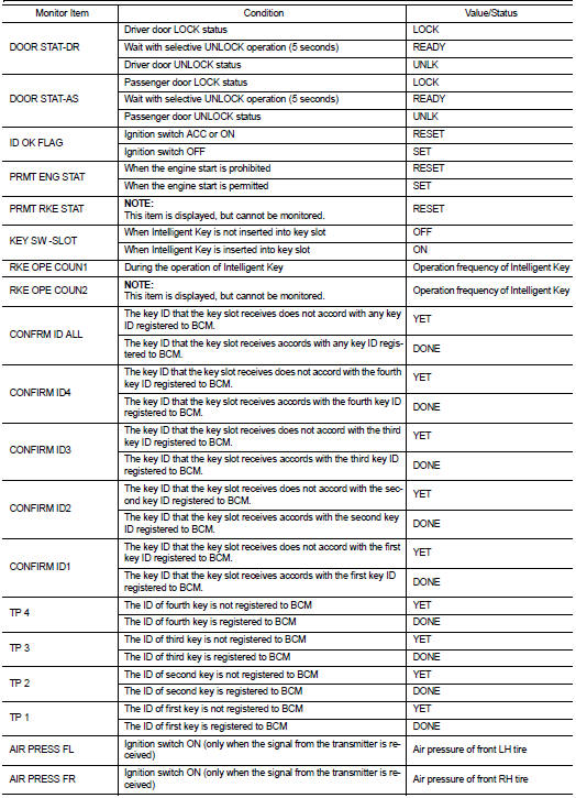
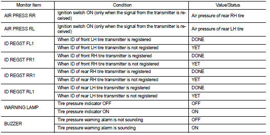
VALUES ON THE DIAGNOSIS TOOL
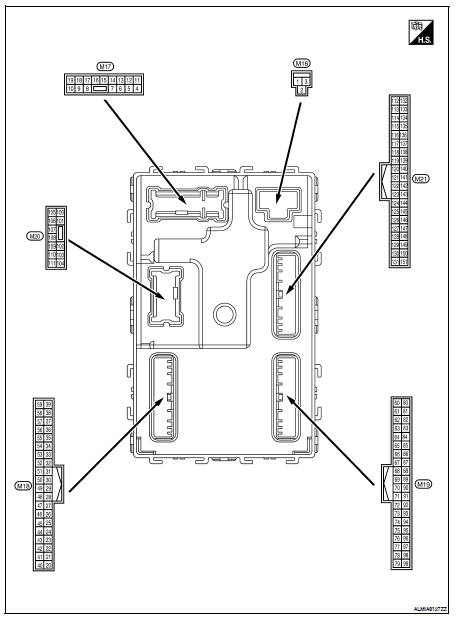
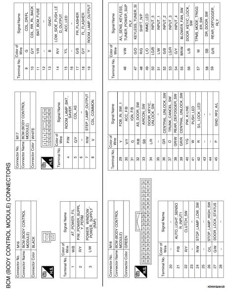
Terminal Layout
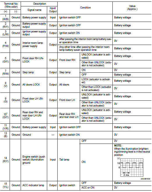
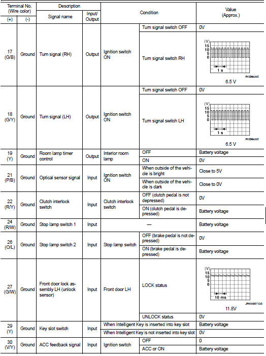
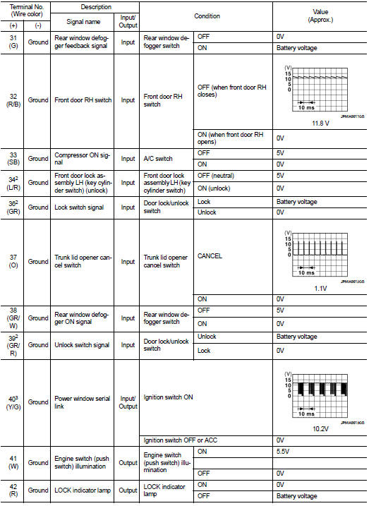
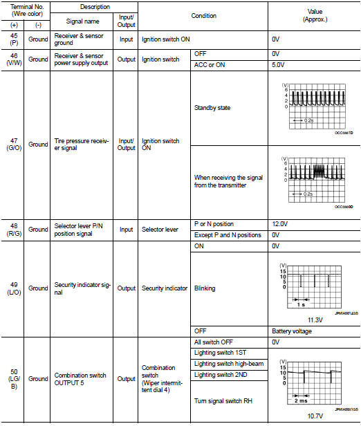
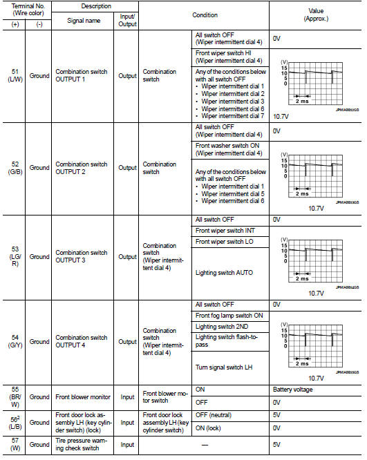
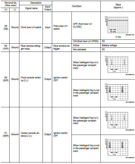
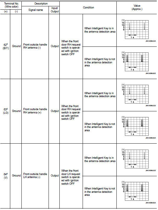
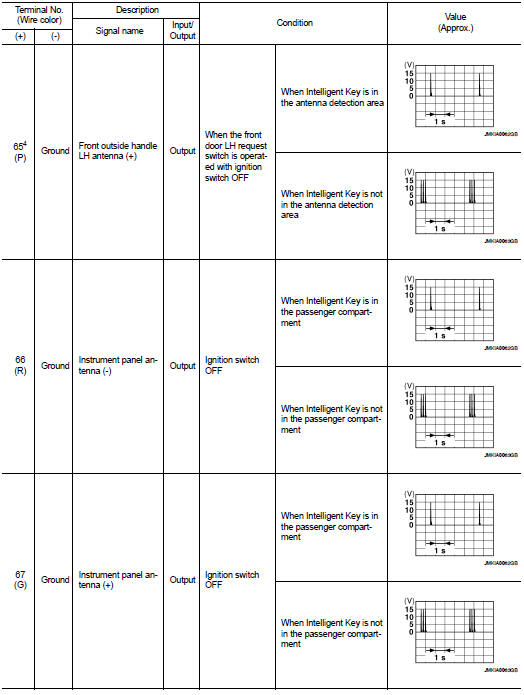
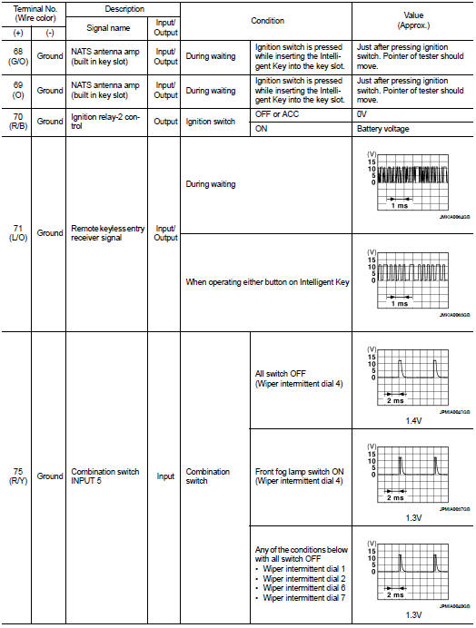
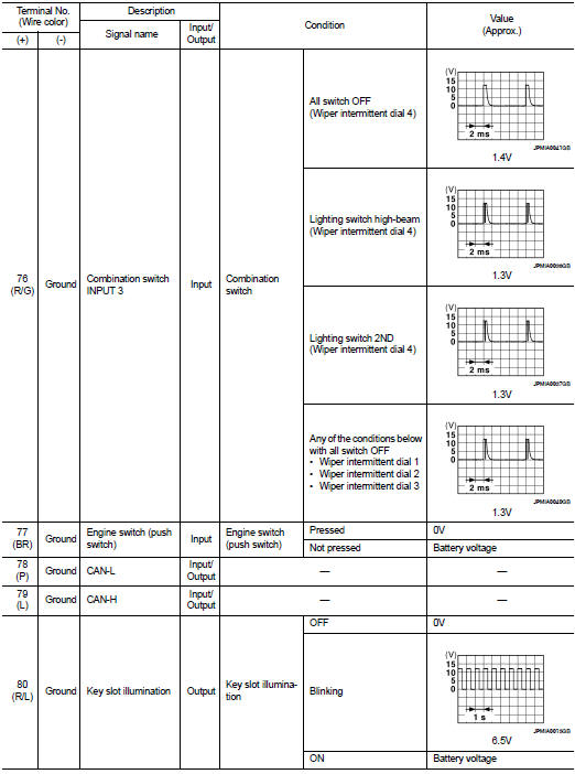
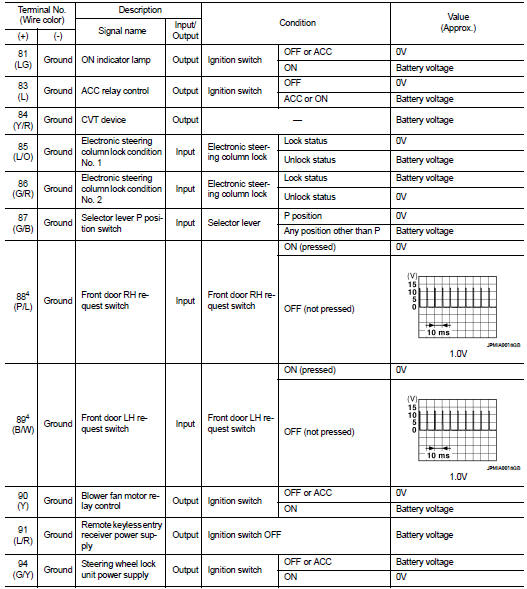
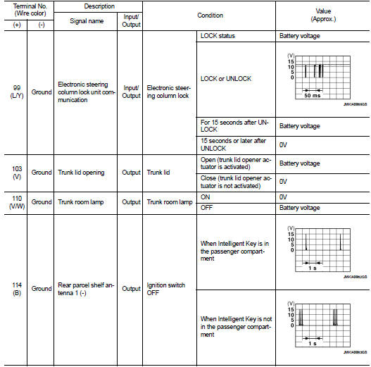
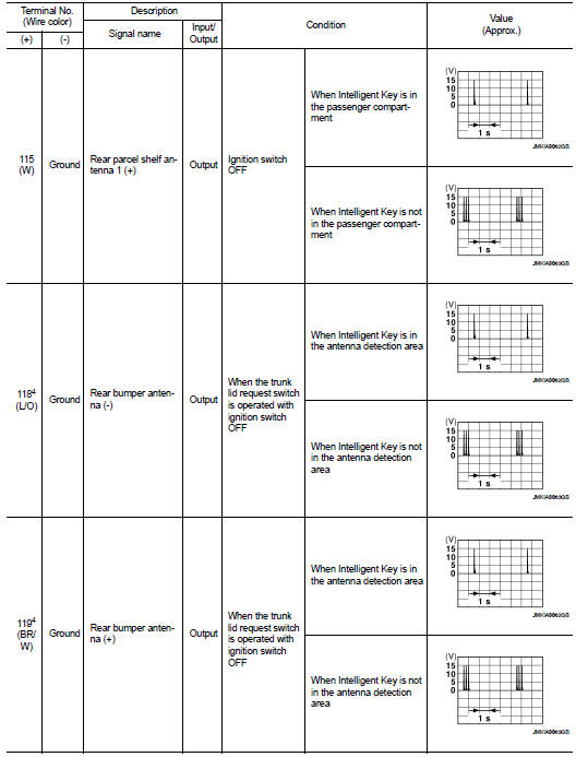
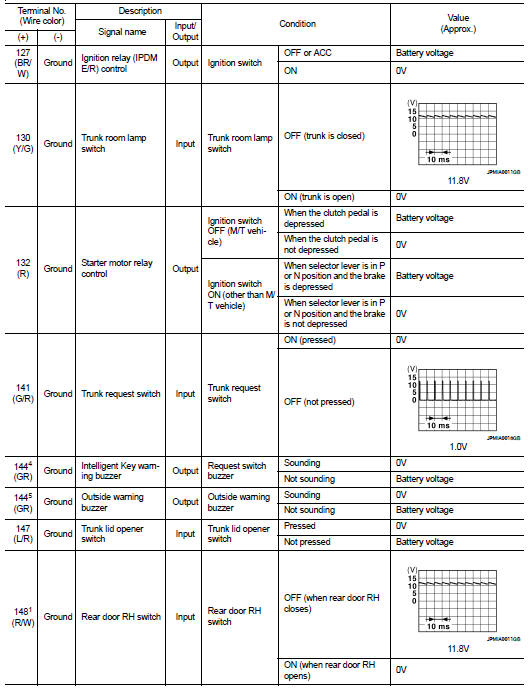
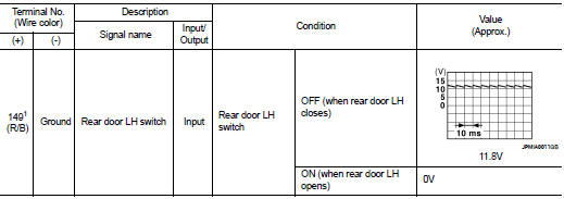
Physical Values
1: Sedan only
2: With LH front window anti-pinch
3: With LH and RH front window anti-pinch
4: With Intelligent Key
5: Without Intelligent Key
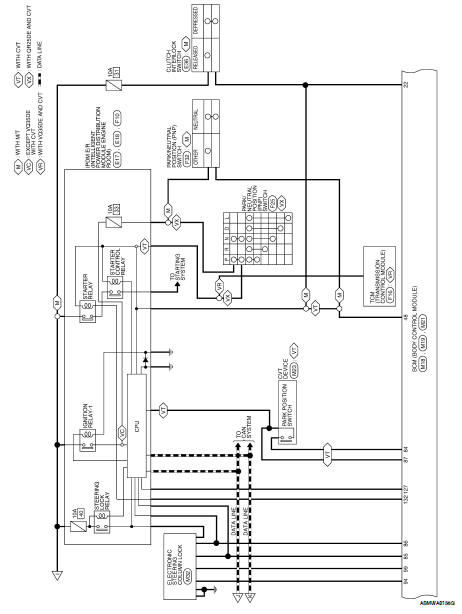
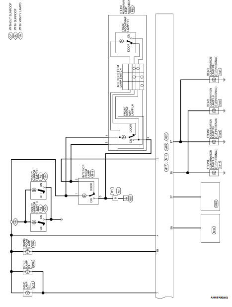
Wiring Diagram-Coupe
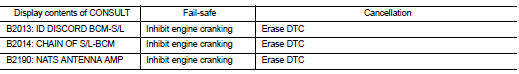
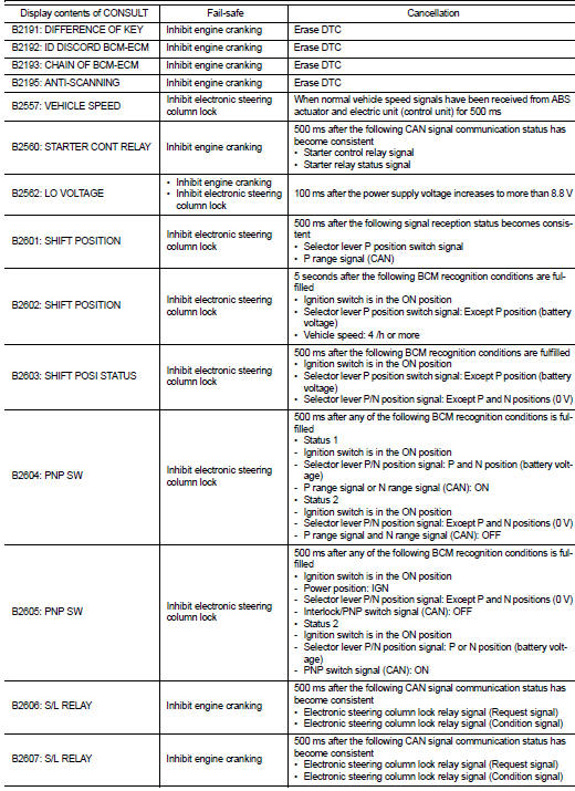
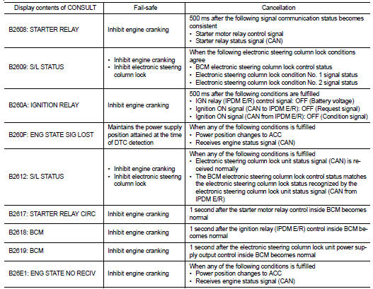
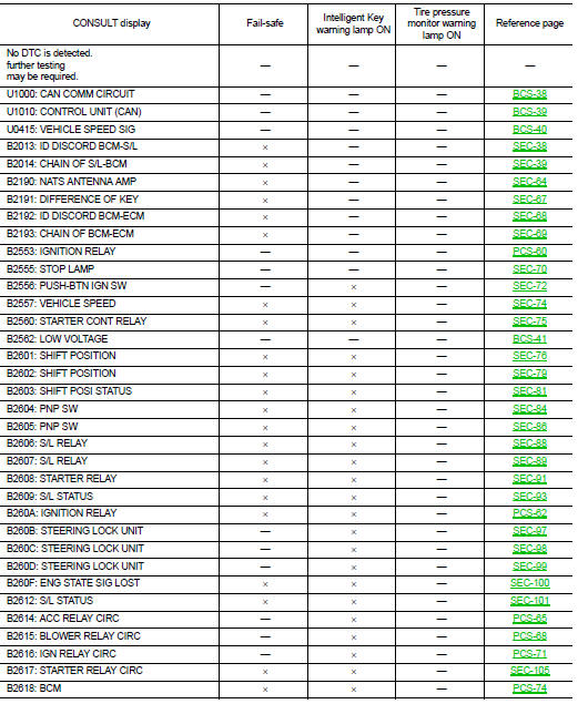
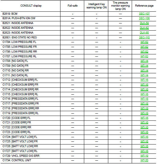
Fail Safe
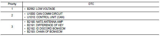
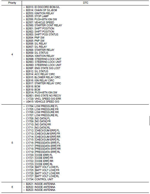
DTC Inspection Priority Chart
If some DTCs are displayed at the same time, perform inspections one by one
based on the following priority
chart.
DTC Index
Details of time display
• CRNT: Displays when there is a malfunction now or after returning to the
normal condition until turning ignition
switch OFF → ON again.
• 1 - 39: Displayed if any previous malfunction is present when current
condition is normal. It increases like 1
→ 2 → 3...38 → 39 after returning to the normal condition whenever ignition
switch OFF → ON. The counter
remains at 39 even if the number of cycles exceeds it. It is counted from 1
again when turning ignition switch
OFF → ON after returning to the normal condition if the malfunction is detected
again.
Reference Value
TERMINAL LAYOUT
PHYSICAL VALUES
MAIN POWER WINDOW AND DOOR LOCK/UNLOCK SWITCH
Wiring Diagram
Fail Safe
FAIL-SAFE CONTROL
Switches to fail-safe control when ma ...
Precaution for Supplemental Restraint System
(SRS) "AIR BAG" and "SEAT BELT PRE-TENSIONER"
The Supplemental Restraint System such as “AIR BAG” and “SEAT BELT PRE-TENSIONERâ ...
 Power window main switch
 Precaution