Nissan Altima (L32) 2007-2012 Service Manual: BCM branch line circuit
Diagnosis Procedure
INSPECTION PROCEDURE
1.CHECK CONNECTOR
1. Turn the ignition switch OFF.
2. Disconnect the battery cable from the negative terminal.
3. Check the terminals and connectors of the BCM for damage, bend and loose
connection (unit side and
connector side).
Is the inspection result normal?
YES >> GO TO 2.
NO >> Repair the terminal and connector.
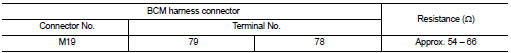
2.CHECK HARNESS FOR OPEN CIRCUIT
1. Disconnect the connector of BCM.
2. Check the resistance between the BCM harness connector terminals.
Is the measurement value within the specification?
YES >> GO TO 3.
NO >> Repair the BCM branch line.
3.CHECK POWER SUPPLY AND GROUND CIRCUIT
Check the power supply and the ground circuit of the BCM. Refer to BCS-42,
"Diagnosis Procedure".
Is the inspection result normal?
YES (Present error)>>Replace the BCM. Refer to BCS-96, "Removal and
Installation".
YES (Past error)>>Error was detected in the BCM branch line.
NO >> Repair the power supply and the ground circuit.
Diagnosis Procedure
1.CHECK AIR BAG DIAGNOSIS SENSOR UNIT
Check the air bag diagnosis sensor unit. Refer to SRC-3, "Work Flow".
Is the inspection result normal?
YES >> Replace t ...
Diagnosis Procedure
INSPECTION PROCEDURE
1.CHECK CONNECTOR
1. Turn the ignition switch OFF.
2. Disconnect the battery cable from the negative terminal.
3. Check the terminals and connectors o ...
Other materials: Child safety
WARNING
Do not allow children to play with the
seat belts. Most seating positions are
equipped with Automatic Locking Retractor
(ALR) mode seat belts. If the seat
belt becomes wrapped around a child’s
neck with the ALR mode activated, the
child can be seriously injured or killed if
the seat belt r ...
Rear-facing child restraint installation
using the seat belts
WARNING
The three-point seat belt with Automatic
Locking Retractor (ALR) must be
used when installing a child restraint.
Failure to use the ALR mode will result
in the child restraint not being properly
secured. The restraint could tip over or
be loose and cause injury to a child in a
sudden stop o ...
Seats
WARNING
Do not ride in a moving vehicle when
the seatback is reclined. This can be
dangerous. The shoulder belt will not
be against your body. In an accident,
you could be thrown into it and receive
neck or other serious injuries.
You could also slide under the lap belt
and receive serious ...
 A-BAG branch line circuit
 DLC branch line circuit