Nissan Altima (L32) 2007-2012 Service Manual: Combination switch output circuit
Diagnosis Procedure
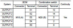
1. CHECK OUTPUT 1 - 5 SYSTEM CIRCUIT FOR OPEN
1. Turn the ignition switch OFF.
2. Disconnect the BCM and combination switch.
3. Check continuity between BCM harness connector and combination
switch harness connector.
Does continuity exist?
YES >> GO TO 2
NO >> Repair or replace harness.
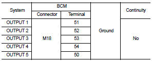
2. CHECK OUTPUT 1 - 5 SYSTEM CIRCUIT FOR SHORT
Check for continuity between BCM harness connector and ground.
Does continuity exist?
YES >> Repair or replace harness.
NO >> GO TO 3
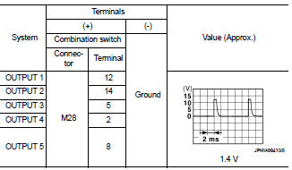
3. CHECK COMBINATION SWITCH OUTPUT VOLTAGE
1. Connect the BCM and combination switch.
2. Turn ON any switch in the system that is malfunctioning.
3. Check voltage between combination switch harness connector
and ground.
Is the measurement normal when any of the switches is turned ON?
YES >> Replace BCM. Refer to BCS-96, "Removal and Installation".
NO >> Replace the combination switch. Refer to WW-121, "Removal and
Installation".
Special Repair Requirement
1. REQUIRED WORK WHEN REPLACING BCM
Initialize control unit. Refer to BCS-6, "CONFIGURATION (BCM) : Special
Repair Requirement".
>> Work End.
Diagnosis Procedure
1. CHECK INPUT 1 - 5 SYSTEM CIRCUIT FOR OPEN
1. Turn the ignition switch OFF.
2. Disconnect the BCM and combination switch.
3. Check continuity between BCM harness connect ...
BCM (BODY CONTROL MODULE)
Reference Value
VALUES ON THE DIAGNOSIS TOOL
Terminal Layout
Physical Values
1: Sedan only
2: With LH front window a ...
Other materials: Intelligent Lane Intervention (I-LI)
(if so equipped)
WARNING
Failure to follow the warnings and instructions
for proper use of the I-LI system
could result in serious injury or
death.
The I-LI system will not steer the vehicle
or prevent loss of control. It is
the driver’s responsibility to stay
alert, drive safely, keep the vehicle in
the tr ...
Vehicle loading information
WARNING
It is extremely dangerous to
ride in a cargo area inside a vehicle.
In a collision, people riding
in these areas are more
likely to be seriously injured or
killed.
Do not allow people to ride in
any area of your vehicle that is
not equipped with seats and
seat belts.
Be sure ever ...
System malfunction
If the I-FCW system malfunctions, it will be
turned off automatically, a chime will
sound, the AEB with Pedestrian Detection
system warning light (yellow) will illuminate
and the warning message [Malfunction]
will appear in the vehicle information
display.
Action to take
If the warning light (yello ...
 Combination switch input circuit
 ECU diagnosis