Nissan Altima (L32) 2007-2012 Service Manual: Compressor
Removal and Installation for Compressor - QR25DE Models
REMOVAL
1. Discharge the refrigerant. Refer to HA-24, "HFC-134a (R-134a) Service Procedure".
2. Remove the drive belt. Refer to EM-16, "Removal and Installation".
3. Remove the engine undercover.
4. Remove the front RH wheel and tire.
5. Remove the side cover from inside the front RH wheel well.
6. Remove the clip and reposition the power steering pipe out of the way.
7. Disconnect the compressor connector.
8. Disconnect the high-pressure flexible hose and low-pressure flexible hose from the compressor.
CAUTION: Cap or wrap the joint of the hose with a suitable material such as vinyl tape to avoid the entry of any contaminants. 9. Remove the compressor bolts, then remove the compressor using power tools.
INSTALLATION
Installation is in the reverse order of removal. CAUTION: • Replace the O-ring of the low-pressure flexible hose and high-pressure flexible hose with new ones, then apply A/C oil to them for installation.
• After charging the A/C refrigerant, check for leaks. Refer to HA-25, "Checking of Refrigerant Leaks".
Removal and Installation for Compressor - VQ35DE Models
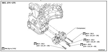
CAUTION: For installation, tighten the compressor bolts in the order as shown.
REMOVAL
1. Discharge the refrigerant. Refer to HA-32, "HFC-134a (R-134a) Service Procedure".
2. Remove the engine cooling fan and shroud assembly. Refer to CO-40, "Removal and Installation".
3. Disconnect the high-pressure flexible hose and low-pressure flexible hose from the compressor.
CAUTION: Cap or wrap the joint of the hose with suitable material such as vinyl tape to avoid the entry of any contaminants.
4. Remove the front RH wheel and tire.
5. Remove the RH engine side undercovers.
6. Disconnect the clamp and reposition the power steering pipe out of the way.
7. Disconnect the compressor connector.
8. Remove the drive belt. Refer to EM-121, "Removal and Installation".
9. Remove the RH compressor bolts..
10. Remove the front compressor bolts using power tool.
11. Disconnect the compressor wire harness clip from the compressor.
12. Remove the compressor.
INSTALLATION
Installation is in the reverse order of removal. CAUTION: • For installation, tighten the compressor bolts in the order as shown.
• Replace the O-rings on the low-pressure flexible hose and high-pressure flexible hose with new ones, then apply A/C oil to them for installation.
• After charging the A/C refrigerant, check for leaks. Refer to HA-25, "Checking of Refrigerant Leaks".
 Refrigeration system
 Low-pressure flexible hose