Nissan Altima (L32) 2007-2012 Service Manual: Cooling system
Cooling Circuit
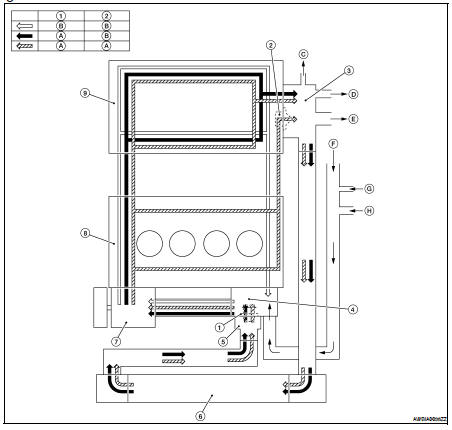
1. Thermostat
2. Water control valve
3. Water control valve housing (Water outlet)
4. Cylinder block (Thermostat housing)
5. Water inlet
6. Radiator
7. Water pump
8. Cylinder block
9. Cylinder head
A. Open
B. Closed
C. To electric throttle control
D. To oil cooler
E. To heater
F. From heater
G. From electric throttle control
H. From oil cooler
Schematic
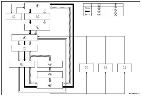
1. Radiator
2. Water inlet
3. Reservoir tank
4. Thermostat
5. Thermostat housing
6. Water pump
7. Cylinder head
8. Cylinder block
9. Water control valve
10. Water control valve housing
11. Heater
12. Oil cooler
13. Electric throttle control
A. Open
B. Closed
Troubleshooting Chart
...
 Function diagnosis
 Overheating cause analysis