Nissan Altima (L32) 2007-2012 Service Manual: Door switch
Description
Detects door open/close condition.
Component Function Check
1.CHECK FUNCTION

Check door switches DOOR SW-DR, DOOR SW-AS in Data Monitor mode with CONSULT-III.
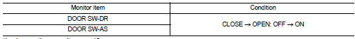
Is the inspection result normal? YES >> Door switch is OK.
NO >> Refer to RF-17, "Diagnosis Procedure".
Diagnosis Procedure
1.CHECK DOOR SWITCH INPUT SIGNAL
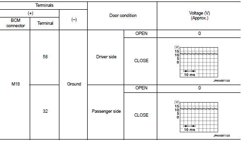
1. Turn ignition switch OFF.
2. Check signal between BCM connector and ground with oscilloscope.
Is the inspection result normal? YES >> GO TO 4
NO >> GO TO 2
2.CHECK DOOR SWITCH CIRCUIT
1. Disconnect BCM connector.
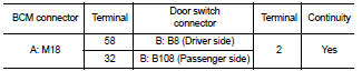
2. Check continuity between BCM connector and door switch connector.
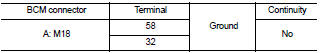
3. Check continuity between BCM connector and ground.
Is the inspection result normal? YES >> GO TO 3
NO >> Repair or replace harness between BCM and door switch.
3.CHECK DOOR SWITCH
Refer to RF-19, "Component Inspection".
Is the inspection result normal? YES >> GO TO 4
NO >> Replace malfunctioning door switch.
4.CHECK INTERMITTENT INCIDENT
Refer to GI-42, "Intermittent Incident".
>> Inspection End.
Component Inspection
1.CHECK DOOR SWITCH
1. Turn ignition switch OFF.
2. Disconnect door switch connector.
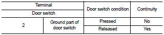
3. Check door switch.
Is the inspection result normal? YES >> Inspection End.
NO >> Replace malfunctioning door switch.
 Power supply and ground circuit
 ECU diagnosis