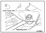
Nissan Altima (L32) 2007-2012 Service Manual: Front lower link
Removal and Installation
Removal
1. Remove the front lower link nut and bolt from the knuckle side
and the adjusting bolt and nut from the suspension member side
using power tools.
• Do not reuse the adjusting nut, use a new adjusting nut for
installation.
2. Remove the front lower link.
Installation
Installation is in the reverse order of removal.
• Do not reuse the adjusting nut, use a new adjusting nut for installation.
• Check the rear wheel alignment and adjust if necessary. Refer to RSU-18, "Rear
Wheel Alignment
(Unladen*)".
Removal and Installation
Removal
1. Loosen the rear lower link bolt and nut from the suspension member side.
2. Support the rear lower link by placing a suitable jack under the knuckle.
3. Rem ...
Removal and Installation
Removal
1. Remove the rear suspension assembly. Refer to RSU-12, "Removal and
Installation".
2. Remove the radius rod using power tools.
Installation
Insta ...
Other materials: Towing a trailer
Do not tow a trailer with your vehicle.
Flat towing
Towing your vehicle with all four wheels on
the ground is sometimes called flat towing.
This method is sometimes used when
towing a vehicle behind a recreational vehicle,
such as a motor home.
CAUTION
Failure to follow these guidelines can
re ...
Power outlet
Instrument Panel
The power outlet is for powering electrical
accessories such as cellular telephones.
It is rated at 12 volt, 120W (10A) maximum.
The power outlet is powered only when the
ignition switch is in the AUTO ACC or ON
position.
CAUTION
The outlet and plug may be hot during
or immedi ...
Steering Assist display and
indicators
Steering Assist status indicator/
warning
Displays the status of the Steering Assist by
the color of the indicator/warning
Steering Assist indicator (gray): Steering
Assist standby
Steering Assist indicator (green): Steering
Assist active
Steering Assist indicator (yellow): Steering
Assis ...


 Rear lower link & coil spring
 Radius rod