Nissan Altima (L32) 2007-2012 Service Manual: Front wiper motor hi circuit
Component Function Check
1. CHECK FRONT WIPER HI OPERATION

1. Start IPDM E/R auto active test. Refer to PCS-14, "Diagnosis Description".
2. Check that the front wiper operates at the HI operation.

1. Select "FRONT WIPER" of IPDM E/R active test item.
2. While operating the test item, check that front wiper HI operation and OFF.

Does the front wiper operate? YES >> The front wiper motor HI circuit is normal.
NO >> Refer to WW-20, "Diagnosis Procedure".
Diagnosis Procedure
1. CHECK FRONT WIPER MOTOR (HI) OUTPUT VOLTAGE

1. Turn the ignition switch OFF.
2. Disconnect front wiper motor.
3. Turn the ignition switch ON.
4. Select "FRONT WIPER" of IPDM E/R active test item.
5. With operating the test item, check voltage between IPDM E/R harness connector and ground.
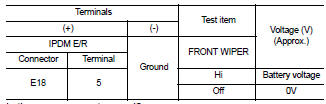
Is the measurement normal? YES >> GO TO 2
NO >> Replace IPDM E/R. Refer to PCS-48, "Removal and Installation".
2. CHECK FRONT WIPER MOTOR (HI) OPEN CIRCUIT
1. Turn the ignition switch OFF.
2. Disconnect IPDM E/R.
3. Check continuity between IPDM E/R harness connector (A) and front wiper motor harness connector (B).
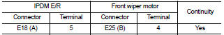
Does continuity exist? YES >> GO TO 3
NO >> Repair or replace harness.
3. CHECK FRONT WIPER MOTOR (HI) SHORT CIRCUIT
Check continuity between IPDM E/R harness connector and ground.
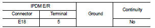
Does continuity exist? YES >> Repair or replace harness.
NO >> Replace front wiper motor. Refer to WW-116, "FRONT WIPER DRIVE ASSEMBLY : Removal and Installation".
 Front wiper motor lo circuit
 Front wiper auto stop signal circuit