Nissan Altima (L32) 2007-2012 Service Manual: Inspection and adjustment
Preliminary Check
1.TIRE PRESSURE
Check all tire pressures. Refer to WT-70, "Tire".
Do tire pressures match specification? YES >> GO TO 2
NO >> Adjust tire pressure to specified value.
2.LOW TIRE PRESSURE WARNING LAMP
Check low tire pressure warning lamp activation.
Does the low tire pressure warning lamp activate for one second when ignition switch is turned ON? YES >> GO TO 3
NO >> GO TO WT-56, "Low Tire Pressure Warning Lamp Does Not Come On When Ignition Switch Is Turned On".
3.BCM CONNECTOR
1. Disconnect BCM harness connectors.
2. Check terminals for damage or loose connection.
3. Reconnect harness connector.
Are BCM connectors damaged or loose? YES >> GO TO 4
NO >> Repair or replace damaged parts.
4.TRANSMITTER ACTIVATION TOOL
Check battery in transmitter activation tool.
Is transmitter activation tool battery fully charged? YES >> Perform SELF-DIAGNOSIS. Refer to WT-52, "Self-Diagnosis (With CONSULT-III)".
NO >> Replace battery in transmitter activation tool.
Transmitter Wake Up Operation
NOTE: This procedure must be done after replacement of a low tire pressure warning transmitter or BCM.
New replacement transmitters are provided "asleep" and must first be "woken up" using Transmitter Activation Tool J-45295 before ID registration can be performed.
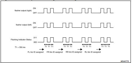
1. Turn ignition switch ON. Push the transmitter activation tool against the tire near the front left transmitter. Press the button for 5 seconds. The hazard warning lamps flash per the following diagram.
Tool number : (J-45295)
2. Repeat this procedure for each tire in the following order: FL, FR, RR, RL.
3. When the BCM finishes assigning each tire ID, the BCM flashes the hazard warning lamps and sends flashing indicator status by CAN according to the following time chart.
4. After completing wake up of all transmitters, make sure low tire pressure warning lamp goes out.
ID Registration Procedure
ID REGISTRATION WITH TRANSMITTER ACTIVATION TOOL
NOTE: This procedure must be done after replacement of a low tire pressure warning transmitter or BCM.
New replacement transmitters are provided "asleep" and must first be "woken up" using Transmitter Activation Tool J-45295 before ID registration can be performed.
1. Connect CONSULT-III.
2. Select "ID REGIST" under BCM.
3. Push the transmitter activation tool against the tire near the front left transmitter. Press the button for 5 seconds.
Tool number : (J-45295)
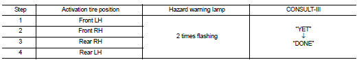
4. Register the IDs in order from FR LH, FR RH, RR RH and RR LH. When ID registration of each wheel has been completed, the hazard warning lamps flash.
5. After completing all ID registrations, press “END” to complete the procedure.
NOTE: Be sure to register all of the IDs in order from FR LH, FR RH, RR RH, to RR LH, or the self-diagnostic results display will not function properly.
ID REGISTRATION WITHOUT TRANSMITTER ACTIVATION TOOL
NOTE:
This procedure must be done after replacement of a low tire pressure warning transmitter or BCM.
New replacement transmitters are provided "asleep" and must first be "woken up" using Transmitter Activation Tool J-45295 before ID registration can be performed.
1. Connect CONSULT-III.
2. Select "ID REGIST" under BCM.
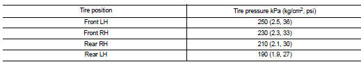
3. Adjust the tire pressures to the values shown in the table and drive the vehicle at 40 km/h (25 MPH) or more for a few minutes.
4. After completing all ID registrations, press “END” to complete the procedure.

5. Inflate all tires to proper pressure. Refer to WT-70, "Tire".
 Diagnosis and repair workflow
 Function diagnosis