Nissan Altima (L32) 2007-2012 Service Manual: Inspection and adjustment
Description and Conditions
DESCRIPTION
The purpose of the operational check is to confirm that the system operates properly.
CONDITIONS: • Engine running and at normal operation temperature.
Operational Check
STEP 1: Check Blower
1. Turn blower control dial clockwise, blower should operate on low speed.
2. Continue turning blower control dial clockwise, and continue checking blower speeds until all speeds are checked.
3. Leave blower on HI speed.
If NG, go to HAC-42, "Diagnosis Procedure".
If OK, continue with next check.
STEP 2: Check Discharge Air
1. Press each mode switch and press DEF (
 ) switch.
2. Each mode position indicator should illuminate.
3. Confirm that discharge air comes out according to the air distribution table. Refer to HAC-14, "System Description".
NOTE:
Confirm that the compressor clutch is engaged (audio or visual inspection) and
intake door is in the FRE
(  ) position when the DEF (
 )
is selected.
)
is selected.
Intake door position is checked in the next step.
If NG, go to HAC-32, "Diagnosis Procedure".
If OK, continue with next check.
STEP 3: Check Recirculation
1. Press REC ( ) switch.
Recirculation indicator should illuminate.
2. Press REC (  ) switch a second
time.
) switch a second
time.
3. Listen for intake door position change (you should hear blower sound change slightly).
If NG, go to HAC-35, "Diagnosis Procedure".
If OK, continue with next check.
STEP 4: Check Temperature Decrease
1. Turn the temperature dial counterclockwise to 18°C (60F°).
2. Check for cold air at discharge air outlets.
If NG, go to HAC-84, "Component Function Check".
If OK, continue with next check.
STEP 5: Check Temperature Increase
1. Turn the temperature dial clockwise to 32°C (90°F).
2. Check for hot air at discharge air outlets.
If NG, go to HAC-92, "Component Function Check".
If OK, continue with next check.
STEP 6: Check AUTO Mode
1. Press the AUTO switch.
2. Confirm that the compressor clutch engages (audio or visual inspection).
(Discharge air and blower speed will depend on ambient, in-vehicle and set temperatures.) If NG, go to HAC-61, "Diagnosis Procedure", then if necessary, HAC-46, "Component Function Check".
If all operational checks are OK (symptom can not be duplicated), go to Refer to Service Manual and perform tests as outlined to simulate driving condition environment. If symptom appears, refer to HAC-83, "Symptom Matrix Chart".
Auxiliary Mechanism Trimmers
TEMPERATURE SETTING TRIMMER
The trimmer compensates for differences in range of ±3°C (±6°F) between temperature setting (displayed digitally) and temperature felt by customer.
Operating procedures for this trimmer are as follows: 1. Begin self-diagnosis STEP-5 mode. Refer to HAC-22, "Diagnosis Description".
2. Turn blower control dial clockwise to set system in auxiliary mode.
3. Display shows “61” in auxiliary mechanism. It takes approximately 3 seconds to enable setting operation.
4. Turn temperature control dial (LH) as desired. Temperature will change at a rate of 0.5°C (1.0°F) each time a dial is turned.
NOTE: • A decimal point is not indicated on the display.
• Negative value is displayed on the LH temperature display.
When battery cable is disconnected or battery voltage is below 10 V, trimmer operation is canceled. Temperature set becomes that of initial condition, i.e. 0°C (0°F).
FOOT POSITION SETTING TRIMMER
D/F1 stop position mode can be set.
Operating procedures for this trimmer are as follows: 1. Begin self-diagnosis STEP-5 mode. Refer to HAC-22, "Diagnosis Description".
2. Turn blower control dial clockwise to set system in auxiliary mode.
3. Press the OFF switch for each mode as desired.
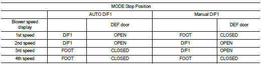
When battery cable is disconnected or battery voltage is below 10 V, trimmer operation is canceled. Foot position mode set becomes that of initial condition.
INLET PORT MEMORY FUNCTION
When ignition switch is turned from OFF to ON, inlet port can be set to AUTO or manual.
Operating procedures for this trimmer are as follows: 1. Begin self-diagnosis STEP-5 mode. Refer to HAC-22, "Diagnosis Description".
2. Turn blower control dial clockwise to set system in auxiliary mode.
3. Press REC ( ) switch as desired.
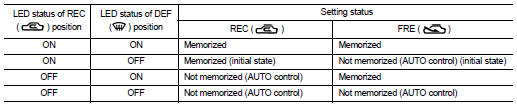
When battery cable is disconnected or battery voltage is below 10 V, memory function is canceled. Memory function set becomes that of initial condition.
 Diagnosis and repair workflow
 Function diagnosis