Nissan Altima (L32) 2007-2012 Service Manual: ODO/TRIP meter
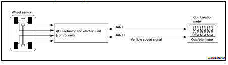
System Diagram
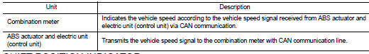
System Description
The vehicle speed signal and the memory signals from the meter memory circuit
are processed by the combination
meter and the mileage is displayed.
HOW TO CHANGE THE DISPLAY FOR ODO/TRIP METER
Refer to Owner's Manual for odo/trip meter operating instructions.
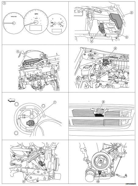
Component Parts Location
1. Combination meter M24
2. IPDM E/R E17, E18, E201, F10
3. ECM E10
4. TCM F16
5. BCM M17, M18, M19, M21 (view with
instrument panel removed)
6. ABS actuator and electric unit (control
unit) E26
7. Fuel level sensor unit and fuel pump
(fuel level sensor) B42 (view with rear
seat and inspection hole cover removed)
8. Ambient sensor E211 (view of front
bumper fascia)
9. Oil pressure switch F41 (QR25DE)
(view with engine removed)
10. Oil pressure switch F41 (VQ35DE)
(view with engine removed)
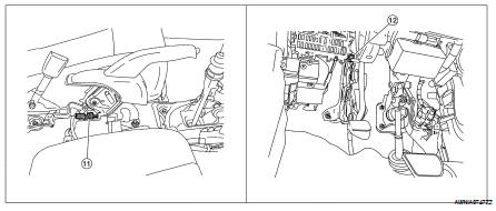
11. Parking brake switch M73
(Sedan with M/T and Coupe)
(view with center console removed)
11. Parking brake switch M73
(Sedan with M/T and Coupe)
(view with center console removed)
Component Description
System Diagram
System Description
The fuel gauge indicates the approximate fuel level in the fuel tank.
The fuel gauge is regulated by the unified meter control unit and a variable
resistor s ...
System Diagram
System Description
The TCM receives CVT indicator signals from the park/neutral position (PNP)
switch. The TCM then sends
CVT position indicator signals to the combination meter ...
Other materials: Traffic Sign Recognition (TSR) (if so equipped)
The TSR system provides the driver with
information about the most recently detected
speed limit. The system captures
the road sign information with the multi-sensing
front camera unit A located on
the windshield in front of the inside rearview
mirror and displays the detected
signs in the vehicle ...
Operating range
The Intelligent Key functions can only be
used when the Intelligent Key is within the
specified operating range.
When the Intelligent Key battery is almost
discharged or strong radio waves are present
near the operating location, the Intelligent
Key system’s operating range becomes
narrower and ...
Air conditioner operation
Start the engine, turn thefan
speed
control dial to the desired position, and
press thebutton to activate the air
conditioner. When the air conditioner is on,
cooling and dehumidifying functions are
added to the heater operation.
The air conditioner cooling function operates
only when the engine i ...
 Fuel gauge
 Shift position indicator