Nissan Altima (L32) 2007-2012 Service Manual: Oil cooler
Removal and Installation
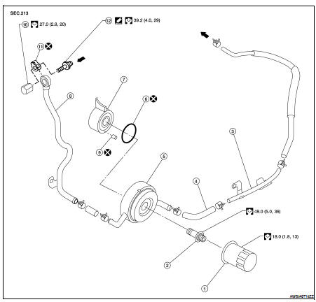
1. Oil filter
2. Oil cooler bolt
3. Water pipe
4. Water hose
5. Oil cooler
6. O-ring
7. Oil pan
8. Water pipe
9. Relief valve
10. Water drain plug
11. Copper gasket
12. Water connector

WARNING: Be careful not to get burned, engine coolant and engine oil may be hot.
CAUTION: • When removing oil cooler, prepare a shop cloth to absorb any engine oil leakage or spillage.
• Completely wipe off any engine oil that adheres to the engine and the vehicle.
REMOVAL
1. Drain engine oil. Refer to LU-23.
2. Drain engine coolant. Refer to CO-35, "Changing Engine Coolant".
• Do not spill coolant on the drive belt.
3. Disconnect water hoses from oil cooler.
4. Remove the oil filter. Refer to LU-25, "Removal and Installation".
5. Remove the oil cooler.
INSPECTION AFTER REMOVAL
1. Check oil cooler for cracks.
2. Check oil cooler for clogging by blowing through coolant inlet. If necessary, replace oil cooler assembly.
Oil Pressure Relief Valve
Inspect oil pressure relief valve for movement, cracks and breaks by pushing the ball. If replacement is necessary, remove valve by prying it out with a suitable tool. Install a new valve in place by tapping it.
INSTALLATION
Installation is in the reverse order of removal.
CAUTION: When installing the oil cooler, align the oil cooler stopper with the stopper of the oil pan.
INSPECTION AFTER INSTALLATION
Start engine and check for leaks of engine oil or coolant.
 Oil pump
 Service data and specifications
(SDS)
Service data and specifications
(SDS)